ArcGIS Pro combines powerful image processing, analysis and visualization capabilities with a practical user interface to enable efficient project workflows. The Imagery tab is the home for image processing workflows and tasks, such as georeferencing and image classification.
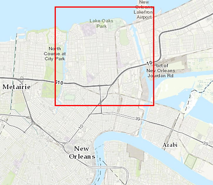
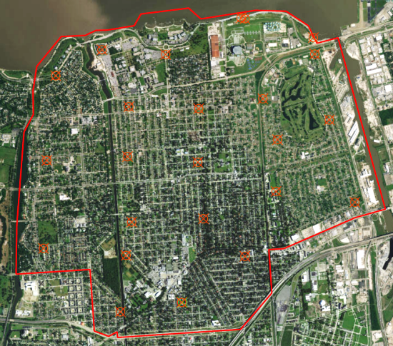
The goal of this workflow is to process multispectral imagery to create an impervious surface map of the Gentilly, Louisiana area for storm water management applications. Gentilly is an area just north of New Orleans, depicted by the red box on the map.
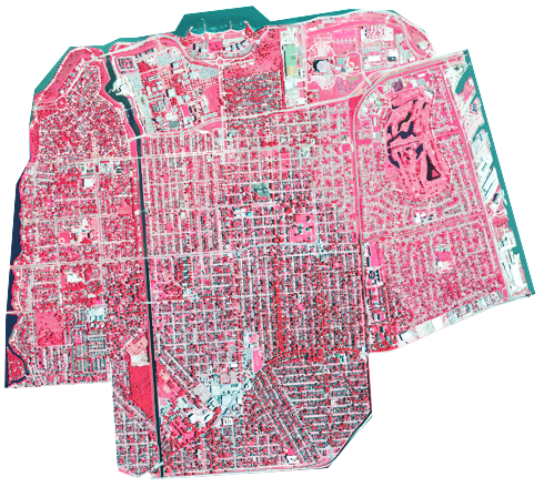
The source image has four spectral bands: near-infrared (NIR), red, green and blue – red, green and blue bands display the imagery as natural color while NIR, Red and Blue displays the imagery as a color infrared composite image. The infrared band is especially valuable for depicting vegetation and is highly recommended for reliable impervious surface mapping, see overview of the infrared image above. Generally, the hue and saturation of the red indicates the type of vegetation while the brightness of the red indicates relative vegetation health or vigor.
Before we classify the image, we need to georeference it to be registered to the existing landbase as described below.
The workflow is comprised of two parts:
Step 1 – Georeference the data so that it is registered to the landbase.
Step 2 – Classify the image based on an impervious surface classification schema.
The georeferencing portion of the workflow is addressed first in this blog, while the image classification portion is addressed in a subsequent blog.
Step 1: Georeferencing
Georeferencing is the process of registering your source imagery to a reference image or vector GIS layer; the reference data is often your existing landbase comprised of orthoimagery and related GIS layers. In this example we will register the new source image to an existing orthoimage by matching control points located on ground features visible in both the source image and the reference image; see Overview of Georeferencing for more details.
The source image is a high resolution satellite image with coarse georeferencing applied and is misaligned with the landbase. If your imagery is not aligned with your landbase, more accurate georeferencing is a vital first step for your project. Georeferencing will adjust your source imagery to the proper geographic location, scale and orientation to fit with your reference data. Once your source imagery is properly aligned, the data and information extracted from it will also be inherently aligned with the landbase.
Most of the work we will be doing is based on the functionality contained on the Georeference tab. We will register the source image to the Imagery Basemap; however, if you have your own orthoimagery basemap, you can use that as your reference image instead.
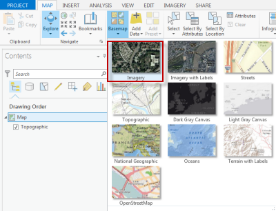
From the Map tab, open the Basemap dropdown and select the Imagery basemap.
Select the source image you want to georeference in the Contents pane. This activates the Georeference button in the IMAGERY tab.
Click the Georeference button to display all the georeferencing functionality.
There are three approaches to georeferencing your source image, an automatic method, an interactive method which gives you more control over the placement of image-to-image control points, and a hybrid method which first automatically georeferences your source image which is then refined by interactively adding more control points to achieve the optimal georeferenced solution.
 If your source imagery is similar to your reference data in terms of location, seasonality, spectral bands, and resolution, use the Auto Georeference button. This will use an image-to-image cross-correlation technique to match similar ground control points between your source and reference images. The initial approximate placement of your source image onto the reference image will greatly affect the success of the automatic ground control point (GCP) creation.
If your source image is significantly misaligned with the reference image, or exhibits significant differences in pixel size or seasonality with the reference image, skip the Auto Georeference step and collect ground control points manually as described below.
 Interactively georeference your image by manually creating coincident ground control points in your source image and reference image using the Add Control Points tool.
When creating control point pairs between your source and reference images, there are several tips to help you perform a good match:
- It is best to collect a few control points in each corner of your source image, and distribute additional control points throughout the image.
- Select points on unmovable ground features, not elevated features
- Permanent man-made features usually provide the best features for control points, not vegetation unless it is a permanent feature, such as the base of a mature tree
- Zoom into an area so you can clearly choose the exact coincident location on both images.
- The L shortcut key toggles the visibility of the source image so that you can see the reference image below it.
Once you have collected several control points, you can choose a transformation. Usually the First Order Transformation – also known as an affine transformation – is sufficient in most cases. The first order transformation requires a minimum of 3 control points, but at least a dozen well-distributed control points will yield a more precise registration between your georeferenced source image and your reference image. Higher order transformations require more control points and will not be available as a choice until the minimum number of control points are collected. Once you have collected several image-to-image control points, select different transformations to see how well your source image is registered to the reference image in real time.
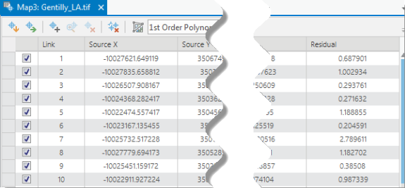
To ensure the be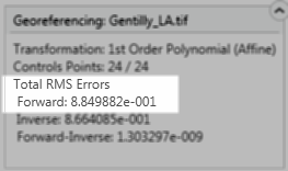 st fit between your georeferenced source image and the reference image, review the overall Root-Mean-Squared (RMS) error in the information box on your display and the residual errors for each control point in the Control Point Table. The total Forward RMS error should be less than the resolution of 1 pixel, and ideally less than half a pixel. In our example, our pixel size is 0.49 and our RMS error is 0.8849, so our RMS error is a bit higher than we would like. This indicates that we need to review and edit some control points in the Control Point Table below.
The Control Point Table allows you to examine the residual error of each control point. Scan the Residual column and look at the highest residual values. You can use the Zoom to Selected tool to zoom into the control point pair. If a particular control point has an unacceptable residual error, you can adjust the point location or add additional points in the same relative area in the image. If you choose to deselect or delete a point from the solution, make sure there are other control points in the same general location to ensure good registration across the whole image and no one area contains the majority of the error.
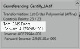 Once you have created sufficient control points distributed across the image and you are satisfied with the overall RMS error and residual error, you can save the image. The Save group on the Georeference tab gives you a few options to save your results: You can Save to the current raster, Save As a new raster dataset, or Export Control Points to a table.
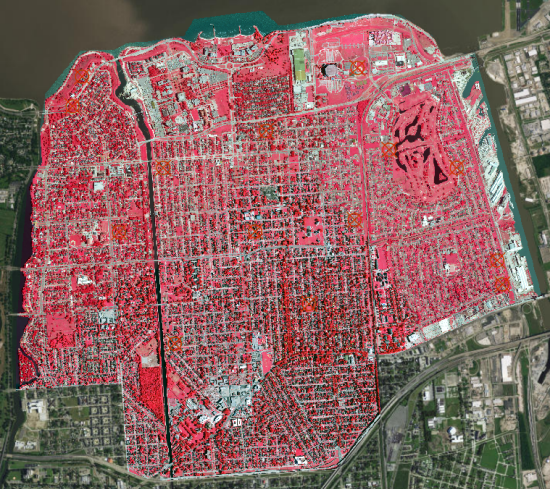
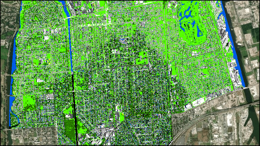
Now your source image basemap has been georeferenced and is ready to be used with your GIS projects such as image classification for identifying impervious surfaces. Image classification is addressed in a subsequent posting of this georeferencing and classification workflow blog.



Commenting is not enabled for this article.