ArcGIS Pro and Autodesk Civil 3D work together to create an accurate 3D view of my projects. Design surfaces from Civil 3D can provide an accurate foundation to the work I do in ArcGIS Pro as well as information visualizations I share as web scenes.
When a corridor is created in Autodesk Civil 3D, a new proposed surface is generated, showing what needs to be cut-and-fill from the existing surface.
Without the proposed surface, the corridor and alignments would be displayed going through the ground or above it. In ArcGIS Pro, to correctly display these elements, you need to import the proposed surface as part of the ground.
The following steps describe how to generate a TIN surface in ArcGIS Pro from the AutoCAD Civil 3D points and add it as ground in a scene.
In preparation, do the following:
- Make sure your DWG file has a valid coordinate system assigned and the elements are in the right location.
Add a layer to the scene and set a definition query
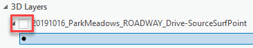
Add the SourceSurfPoint feature class from you DWG into a Local Scene.
Note: As this layer may have a significant number of points, turn off the visibility for now. It will save draw time.
The layer has points for all the surfaces in the DWG file. You have to create a filter to display only the points of the proposed surface that you need.
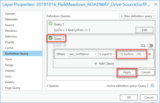
In the Layer Properties palette, set a Definition Query of the layer to be “aec_surfName is Equal To <name of the surface>”. (If you turned off visibility in step 1, turn it on now.)
Note: You can find the unique value of the surfaces from the drop-down list. You should know from the DWG file what the name of the surface is that you will be using.
The points for that surface will be displayed.

Create a TIN surface from the Civil 3D points
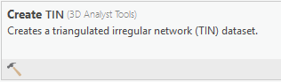
From the geoprocessing tools, select Create TIN.
Run the tool using the SourceSurfPoint layer as part of the Input Features in the Input Feature Class group, and leave the rest with the default values.
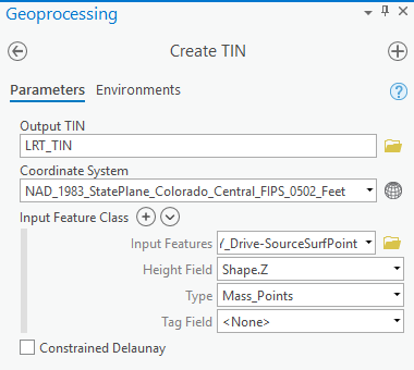
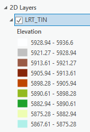
The new TIN surface is added to the 2D Layers and rendered into the scene.
The Create TIN tool extends the surface. This may generate extra, unwanted triangles. Add your output TIN to a Map and use the TIN Editor tools to correct the output.
Add the TIN as ground in the scene
After creating and editing the Tin, return to your Local Scene.
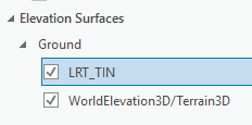
From the scene, in the Contents pane, select Add Elevation Source.
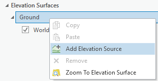
Then select the TIN.
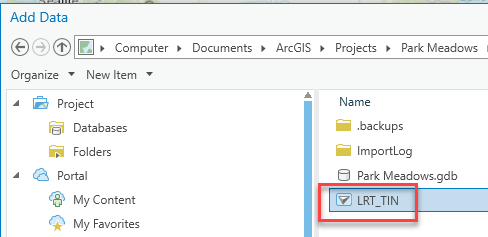
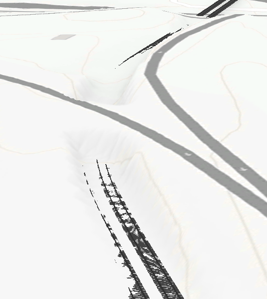
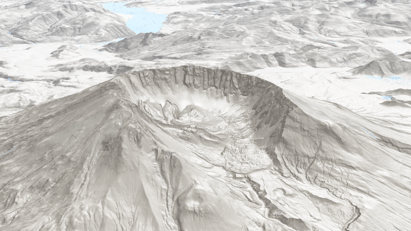
The TIN is added to the ground, and is rendered in the scene, showing the new shape of the ground.
Note: Make sure the new TIN is above the WorldElevation3D file in the content; if not, it will be rendered below the existing terrain.
You can see the new ground, and the AEC elements displayed along it.


Article Discussion: