In ArcGIS Pro 2.7, a couple of new feature classes that are read from the Autodesk Civil 3D files became supported. They are the Multipatch representation of the Gravity Network and the Pressure Network.
These new feature classes enhance the graphic representation of those networks, providing an accurate visualization of the parts that constitute them, based on the parts catalogs that were defined when they were created in Civil 3D.
Rendering these feature classes in a scene is ideal for a Digital Twin representation, which can later be published to ArcGIS Online.
Each of these classes content the totality of the network, which is composed of different parts, where the Gravity Network includes the structures and pipes and the Pressure Network includes the fittings, appurtenance, and pressure pipes. The consolidation of these elements in one feature class created the need to simplify their attributes to a reduced set in which only the common properties were included.
This consolidation of elements and reduced set of attributes is in contrast to the feature classes that represent the individual elements of the networks (pipe, structure, fitting, and so on) as points and lines, because they can be handled as individual feature layers, and each has the full set of AEC attributes that can be displayed alongside the elements. The Multipatch representation is focused mainly on visualization.
But there are some steps that can be followed to enhance the deployment of the GravityNetwork and PressureNetwork feature classes, which can be represented as individual components of the networks with their full set of AEC attributes, providing the best of both worlds.
These steps consist of creating filters on several instances of the feature layers, and then making a table join with the corresponding feature class to expand the attributes.
The following steps describe how to do this with the GravityNetwork feature class, but they will be the same for PressureNetwork.
Create individual feature layers from the GravityNetwork feature class
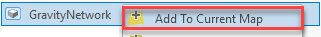
In ArcGIS Pro, create a new scene, and from the Catalog pane, expand your Autodesk Civil 3D file and add the GravityNetwork feature class to the scene.
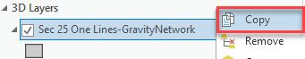
In the Contents pane, select the new feature layer and copy it.
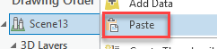
Next, paste it.
Note: When you follow these steps with the Pressure Network. The PressureNetwork feature class is composed of three types of elements (PressurePipe, Fitting, and Appurtenance). Each feature layer will become one of these parts.
Rename them with the name of each part:
- GravityNetwork-Pipe
- GravityNetwork-Structure
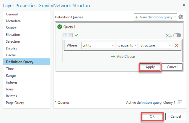
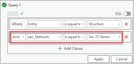
Select the Structure feature layer and go to the layer properties. Click New definition query, and make the new query active.
In the new clause, select the Entity attribute; select is equal to as the operator; and from the last drop-down list, select Structure.
Click Apply and click OK.
Repeat these steps for the other feature layer, selecting Pipe from the last drop-down list.
After this, each individual feature layer will represent an individual entity.
Note: If you have more than one network, you need to add an extra filter by the aec_network attribute if you want to make a distinction for each network.
Add a table join
To extend the attributes, you need to create table join with the Structure and Pipe feature classes.
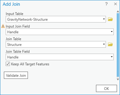
To add the join, select the Structure feature layer where you created the filter in the previous step, and select Joins and Relates > Add Join.

For Input Join Field, select Handle. For Join Table, you can browse to the file location and select Structure, or you can add Structure to the table of contents from the Catalog pane, and it will become available in the drop-down list. After selecting Join Table, the Join Table Field is populated automatically.
Press OK, and the join is created.
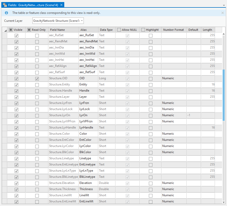
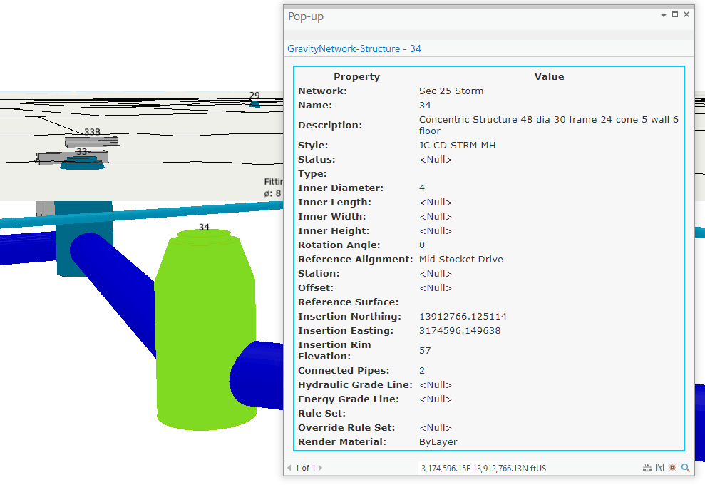
Now all the attributes are available in the GravityNetwork-Structure feature class.
Next, you’ll repeat the steps for the GravityNetwork-Pipe Feature Layer.
Once this is completed, you can add the other attributes in the pop-up’s definition to make them available when you click them. Consider that some of the attribute will be duplicated in this case.
Keep in mind that if you have some Arcade code in your symbology definition, you might need to update the attribute name (the default symbology for GravityNetwork and PressureNetwork uses Arcade to define the display color).

Article Discussion: