In ArcGIS Pro 3.4 we have introduced three new templates that allow you to generate attribute rules tailored for specific workflows. We curated a selection of commonly used attribute rules and created a familiar geoprocessing tool experience that guides you through their creation. Attribute rule templates not only speed up the generation of these rules but also makes them more accessible for users who may not have prior knowledge of Arcade scripting.
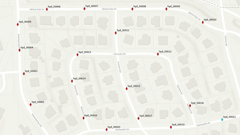
The Generate Symbol Rotation template attribute rule tool allows us to rotate a point feature symbol that intersects with line features. This blog describes a workflow for creating and utilizing a Generate Symbol Rotation template attribute rule to steer some vehicles in the right direction in the suburbs of Boston, Massachusetts. Imagine placing down some fire hydrant point features on a map and seeing the following behavior:
In the GIS world, symbols help us tell a story about the data we’re displaying on our maps. For example, colors can represent different road types (e.g., highways, county roads, local roads, etc.). Symbols can also represent various objects or points of interest such as vehicles and gas stations. A static symbol isn’t always enough to convey the story we want to tell. The orientation of symbols can provide us with critical context about the direction that objects in the real world are facing. In the case of vehicles, we not only want to know where the vehicles are, but also the direction that they’re traveling in.
Manually calculating the directionality for each point feature that intersects a line is a time-consuming process and is prone to errors.
Thankfully, the Generate Symbol Rotation template attribute rule can automatically determine the directionality of point symbols for us based on how those points intersect with line features. After creating the template attribute rule, using it is as easy as configuring some symbology properties related to rotation, enabling snapping, and creating some point features on a map!
Here’s a brief overview video of the Generate Symbol Rotation Attribute Rule tool:
Utilizing the Generate Symbol Rotation Tool
Review Generate Symbol Rotation Data
Note: Attribute Rules require an ArcGIS Pro Standard or Advanced license level. To learn more please refer to the ArcGIS Pro license levels help documentation.
- Download the TemplateARs_SymbolRotation.ppkx project package file and then click on the file to open the TemplateARs_SymbolRotation project. This project contains data to step through the workflow in this blog.
- The project opens with the Vehicle Locations map active. There are two feature classes in the map: a streets layer represented by line features and a vehicles layer represented by point features.
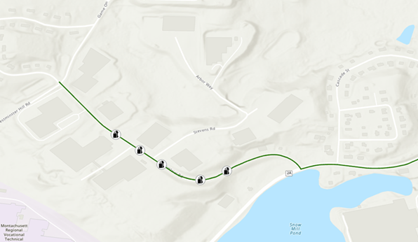
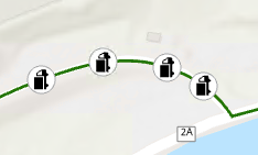
The vehicle point symbols in the map above are incorrectly oriented; the symbols do not follow the direction of travel on the road. To keep things simple, we’ll say that we have a one-way road that goes from left to right. This gives us a clear-cut objective:
Vehicles should face the direction of travel.
Right click on our Vehicles layer in the Contents pane and on the Data Design context menu click Attribute Rules to open the Attribute Rules view.
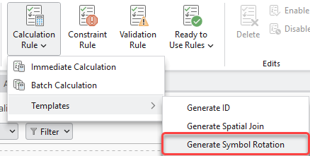
In the Attribute Rules view click on the bottom half of the Calculation Rule button in the ribbon. From the context menu select Templates > Generate Symbol Rotation. The Generate Symbol Rotations Geoprocessing Tool dialog opens.
Tool Overview
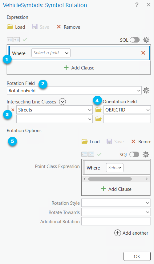
Here are the parameters for the tool and how we’ll fill them out:
- The optional Expression parameter allows us to apply a where clause expression that limits the features the attribute rule will be applied to. The rule will not run unless the conditions of the where clause are satisfied.
- The Rotation Field parameter is the field that stores the rotation value. We have a field conveniently named RotationField for this.
- The Intersecting Line Classes parameter allows us to choose the line feature classes that the point feature class intersects with. Let’s choose the Streets feature class. The Orientation Field is a numeric field used as a tiebreaker if a point intersects with multiple lines. When multiple features occupy the same feature space then the order in which the feature classes are chosen in addition to the orientation field determines which line feature is used for the intersection. By default, the orientation field is set to OBJECTID which is what we will use for our workflow.
- The Rotations Option parameter allows us to configure how point features should rotate when they intersect with line features. We can configure multiple rotation options based on attributes in the point class. For instance, different vehicle types could rotate differently. There are four sub-parameters for a rotation option:
-
- The Point Class Expression allows us to apply a where clause expression on attributes in the point class for which the rotation option should be enforced on. By default, no expression is provided (i.e., the rotation option is applied to all points). If you have multiple rotation options configured, this parameter is helpful in specifying which features a rotation option is applicable for.
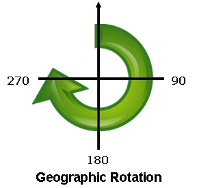
- The Rotation Style specifies how the direction of the rotation is measured. There are two types:
- Arithmetic – the rotation starts at zero in the east direction and is calculated counterclockwise. This is default.
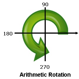
- Geographic – the rotation will start at zero in the north direction and is calculated clockwise
- Rotate Towards specifies whether the feature will be oriented towards maximum or minimum Orientation Field. There are two options:
- Minimum – The feature will be oriented toward the minimum value. This is default (i.e., the larger orientation field value “wins”).
- Maximum – The feature will be oriented toward the maximum value.
- Additional Rotation allows you to add to the calculated rotation value. By default, this value is set to zero.
- For our purposes, we will leave the default values in the Rotation Options parameter.
Once you’re finished filling out the tool parameters, click OK at the bottom of the dialog.
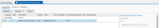
In the Attribute Rules Data Design View, we see that a new calculation rule has been added to the grid called “SymbolRotation”. Let’s rename it to “Vehicle Direction of Travel”.
If you scroll down to the Expression in the Details Pane you can see the Arcade Expression that was generated. It looks like this:
Click here to view a Generate Symbol Rotation Template Attribute Rule Arcade Expression
/*
where_clause (Text): The expression to filter with.
options (Array): The rotation options.
  where_clause (Text): The SQL expression to apply rotation to.
  is_geographic (Boolean): Set to true if the rotation setting is set to geographic in the layer properties.
  additional_rotation (Number): Set the counter-clockwise spin angle used for the symbol in the symbology options.
  rotate_towards (Text): When there are 2 intersecting lines, sort by orientation_field and use the min/max value.
  line_classes (Array): The classes to query.
    class_name (Text): The name of the feature set to query.
    where_clause (Text): The SQL expression to filter class_name.
    orientation_field (Text): The field to orient towards.
*/
var rule_settings = {
  'where_clause': null,
  'options': [
    {
      'where_clause': null,
      'is_geographic': false,
      'additional_rotation': 0,
      'rotate_towards': 'min',
      'line_classes': [
        {
          'class_name': 'Streets',
          'where_clause': null,
          'orientation_field': 'OBJECTID',
        },
      ],
    },
  ],
};

function get_feature_set(key) {
  return Decode(
    key,
    'Streets', FeatureSetByName($datastore, 'Streets_MA', ['OBJECTID'], true),
    null
  );
}

function IsEmpty2(value) {
  var type = TypeOf(value);
  if (type == '') {
    return true; // null
  } else if (type == 'Boolean') {
    return !value;
  } else if (type == 'String') {
    return IsEmpty(value);
  } else if (
    (type == 'Array') ||
    (type == 'Dictionary') ||
    (type == 'FeatureSet')
  ) {
    for (var x in value) {
      return false;
    }
    return true;
  } else if (type == 'Number') {
    return IsNan(value);
  } else if (type == 'Point') {
    return IsNan(value.x);
  } else if (type == 'Multipoint') {
    return Count(value.points) == 0;
  } else if (type == 'Polyline') {
    return Count(value.paths) == 0;
  } else if (type == 'Polygon') {
    return Count(value.rings) == 0;
  } else if (type == 'Extent') {
    return IsNan(value.xmin);
  } else if (
    (type == 'Feature') ||
    (type == 'DateOnly') ||
    (type == 'Time') ||
    (type == 'Date') ||
    (type == 'FeatureSetCollection') ||
    (type == 'Portal') ||
    (type == 'Function')
  ) {
    return false
  }
  return null;
}

function features_to_featureset(features) {
  // Converts features array to feature set.
  if (TypeOf(features) == 'FeatureSet') {
    return features;
  }
  var rows = [];
  var feat, feat_dict;
  for (var i in features) {
    feat = features[i];
    feat_dict = {
      '__oid__': i + 1, // Incrementing OID field.
    };
    for (var j in feat) {
      feat_dict[j] = feat[j];
    }
    Push(rows, {
      'attributes': feat_dict,
    });
  }
  if (IsEmpty(feat)) {
    return;
  }

  // Add OID field to schema.
  var feat_schema = Array(Schema(feat).fields);
  Push(feat_schema, {
    'name': '__oid__',
    'type': 'esriFieldTypeInteger',
  });
  return FeatureSet({
    'fields': feat_schema,
    'features': rows,
  });

}

function count_features(features, where_clause) {
  // count features that match where_clause
  if (IsEmpty2(features)) {
    return 0;
  }
  if (IsEmpty(where_clause)) {
    return Count(features);
  }
  var fs = features_to_featureset(features);
  if (IsEmpty(fs)) {
    return 0;
  }
  return Count(Filter(fs, where_clause));
}

function get_unit_code(unit) {
  // Converts unit string to unit code
  if (IsEmpty(unit)) {
    return
  }

  var u = Lower(Replace(Replace(Replace(unit, ' ', ''), '-', ''), '_', ''));
  // US / INT suffix differentiates the unit code. If no suffix, then it defaults to US Survey.
  var international = false;
  if (Right(u, 2) == 'us') {
    u = Left(u, Count(u) - 2);
  } else if (Right(u, 3) == 'int' && u != 'point') {
    u = Left(u, Count(u) - 3);
    international = true;
  }
  if (Right(u, 1) == 's' && u != 'inches') { // plural
    u = Left(u, Count(u) - 1);
  }
  return When(
    // Metric
    u == 'km' || u == 'kilometer', 9036,
    u == 'm' || u == 'meter', 9001,
    u == 'dm' || u == 'decimeter', 109005,
    u == 'cm' || u == 'centimeter', 1033,
    u == 'mm' || u == 'millimeter', 1025,

    // US Survey / International
    u == 'nmi' || u == 'nauticalmile', IIf(international, 9030, 109012),
    u == 'mi' || u == 'mile', IIf(international, 9093, 9035),
    u == 'yd' || u == 'yard', IIf(international, 9096, 109002),
    u == 'ft' || u == 'foot' || u == 'feet', IIf(international, 9002, 9003),
    u == 'in' || u == 'inch' || u == 'inches', IIf(international, 109008, 109009),

    // Misc
    u == 'dd' || u == 'deg' || u == 'degree' || u == 'decimaldegree', 9102,
    u == 'pt' || u == 'point', 109016,

    // Default
    null,
  )

}

function apply_sql_spatial_filter(feature_set, options) {
  // Applies optional spatial/attribute filters and OrderBy clause to feature_set.
  var spatialFilter = Decode(
    Lower(DefaultValue(options, 'spatial_operator', '')),
    'intersects', Intersects,
    'contains', Contains,
    'crosses', Crosses,
    'envelopeintersects', EnvelopeIntersects,
    'intersects', Intersects,
    'overlaps', Overlaps,
    'touches', Touches,
    'within', Within,
    null
  );

  var geo = DefaultValue(options, 'input_geometry', null);
  if (!IsEmpty(spatialFilter) && !IsEmpty2(geo)) {
    if (!IsEmpty(DefaultValue(options, 'search_distance', null))) {
      geo = Buffer(geo, options.search_distance, get_unit_code(options.search_units));
    }
    feature_set = spatialFilter(feature_set, geo);
  }
  if (!IsEmpty(DefaultValue(options, 'where_clause', null))) {
    feature_set = Filter(feature_set, options.where_clause);
  }
  if (!IsEmpty(DefaultValue(options, 'order_by_clause', null))) {
    feature_set = OrderBy(feature_set, options.order_by_clause);
  }
  return feature_set;
}

if (count_features([$feature], DefaultValue(rule_settings, 'where_clause', null)) != 1) {
  return;
}


Expects($feature, 'RotationField');

if (!IsEmpty($feature.RotationField)) {
  return;
}

var feature_geometry = Geometry($feature);
if (IsEmpty2(feature_geometry)) {
  return;
}

function extract_angles(line_class) {
  var envelope = Extent(Buffer($feature, 0.01, 'meter')); // Buffer by small amount to extract segment.
  var line_fs = apply_sql_spatial_filter(
    get_feature_set(line_class.class_name), {
      'spatial_operator': 'Intersects',
      'input_geometry': Geometry($feature),
      'where_clause': line_class.where_clause,
      'order_by_clause': 'ObjectID ASC',
    }
  )

  var found_angles = [];
  var angle_value;
  var null_val = IIf(rule_settings.rotate_towards == 'max', -Infinity, Infinity);
  for (var line in line_fs) {
    var segment = Clip(line, envelope).paths[0];
    if (Equals(segment[0], feature_geometry)) {
      angle_value = Angle(segment[0], segment[1]); // start point
    } else if (Equals(segment[-1], feature_geometry)) {
      angle_value = Angle(segment[-2], segment[-1]); // end point
    } else {
      angle_value = Angle(segment[0], segment[-1]); // midspan
    }

    if (rule_settings.is_geographic) {
      angle_value = (450 - angle_value) % 360;
    }
    angle_value = (angle_value + rule_settings.additional_rotation) % 360;
    Push(found_angles, {
      'angle': angle_value,
      'orientation': DefaultValue(line[line_class.orientation_field], null_val)
    });
  }
  return found_angles;
}

function collect_angles() {
  var all_angles = [];
  var fs = features_to_featureset([$feature]);

  for (var i in rule_settings.options) {
    var options = rule_settings.options[i];
    if (count_features(fs, options.where_clause) == 1) {
      rule_settings.is_geographic = options.is_geographic;
      rule_settings.additional_rotation = options.additional_rotation;
      rule_settings.rotate_towards = options.rotate_towards;
      for (var j in options.line_classes) {
        all_angles = Splice(all_angles, extract_angles(options.line_classes[j]));
      }
      break;
    }
  }
  return all_angles
}

function angle_sort(a, b) {
  return When(
    a.orientation < b.orientation, -1,
    a.orientation > b.orientation, 1,
    0 // equal
  );
}

function main() {
  var angles = Sort(collect_angles(), angle_sort);
  if (IsEmpty2(angles)) {
    return;
  }
  return angles[IIf(rule_settings.rotate_towards == 'min', 0, -1)]['angle'];
}

return main();
Review and Modify the Generated Rule
In the Attribute Rules tab of the ribbon click the Save button.
Close the Attribute Rules Data Design View and head back to the map. Go to the Edit tab in the ribbon. Enable snapping and click on the Create button. Place a vehicle point on top of one of the streets. Nothing seems to have happened! Or did it? Let’s investigate further!
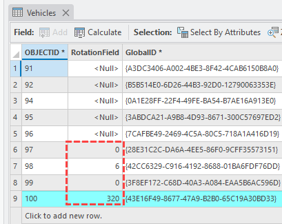
In the Contents pane right click on the Vehicles layer and open its Attributes Table. Notice that the rotation field for the point features we just created are not null. They are a integer value in degrees.
Configuring a Point Layer’s Symbology to Visualize its Symbol Rotation
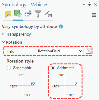
To visualize the rotation values on our point layer, we need to configure its symbology:
- In the Contents pane right click on the Vehicles layer and select Symbology.
- In the Symbology Pane switch to the Vary Symbology by Attribute
- Expand the collapsible section for
- Set the field parameter to RotationField
- Leave the other settings as default. Close the pane.
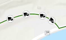
And just like that our vehicle points are rotated!
Before changing the symbology settings:
After changing the symbology settings:
Generate Symbol Rotation template attribute rules are only supported on point feature classes intersecting with line feature classes. Let’s think about why. Point features do not give us the context regarding their directionality. There are scenarios such as the one in our example above where the direction of point features is essential to ensuring data integrity. A logistics company, for instance, doesn’t only want to know where their delivery vehicles are located; they also want to know which direction their vehicles are traveling.
On the other hand, line and polygon features give us relatively static interpretations of directionality. The line features that represent the roads in our example aren’t changing any time soon. They tell us exactly where the road is!
Conclusion
The Generate Symbol Rotation template rule brings one of the most used attribute rules into an easy to use, wizard-like experience. With just a few clicks you can get the correct symbology for your features. And all with no prior knowledge of Arcade needed to use it.
We’d love to hear your feedback regarding the Generate Symbol Rotation template attribute rule! We encourage you to share your thoughts about it or any other attribute rule and data management topics that come to mind on the ArcGIS Ideas page!
FAQs
Do I need a specific ArcGIS Pro license level to generate template attribute rules?
Yes, you will need either an ArcGIS Pro Standard or Advanced license level to utilize template attribute rules.
What are the differences between generating a template attribute rule from the Attribute Rules Data Design view versus from the Geoprocessing pane?
If you generate a template attribute rule from the Attribute Rule Data Design view for a particular feature class, the rule is added directly to the grid in the design view. Prior to saving the rule, you may make edits to the rule via the Details pane.
On the other hand, if you use the template attribute rule geoprocessing tool, you must import the .csv file of the attribute rule generated by the tool to the class you specified in the Input Table parameter. The .csv file containing the attribute rule is stored in the path specified in the Output Folder parameter.
What are the differences between Attribute Rule Templates and Ready to Use Rules?
Template attribute rules can be used to generate Calculation rules using geoprocessing tools. After generating a template attribute rule a user can modify the Arcade script associated with it and any other attribute rule properties via the Details pane.
Ready to Use Rules require a Data Reviewer license. They can be used to generate Constraint and Validation reviewer rules from directly within the Attribute Rules Data Design view. Reviewer rules are used to detect features that do not comply with established data quality requirements defined by your organization. To learn more about reviewer rules please visit Manage reviewer rules in a geodatabase.
Where can I learn more about Generate Symbol Rotation template attribute rules?
The following online help documents are useful in more about Generate Symbol Rotation template attribute rules:
- Template attribute rules – Generate Symbol Rotation
- Generate Symbol Rotation Attribute Rule Geoprocessing Tool
Commenting is not enabled for this article.