From bright deserts and wadis in the Middle East to mangrove coasts in West Africa and monsoon‑prone corridors across Asia, DTM accuracy depends on smart workflow choices and pragmatic performance tactics. This blog outlines three proven ArcGIS Pro paths.
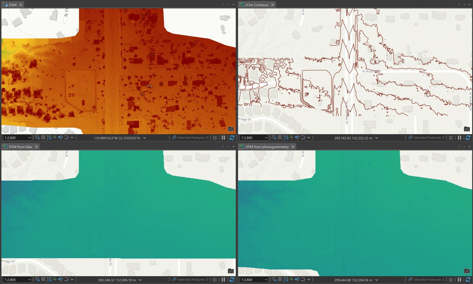
First, here’s a quick reminder of what a DTM is – A Digital Terrain Model (DTM) represents the bare-earth surface, excluding trees, buildings, and other surface objects. It differs from other raster types such as Digital Surface Models (DSMs), which include the elevations of natural and built features, and Digital Elevation Models (DEMs), which may refer to either DTMs or DSMs depending on context. DTMs are essential for hydrological modeling, terrain analysis, and other applications requiring accurate ground elevation data.
Three practical paths to a DTM:
- Generate a DTM directly from an Ortho Mapping or Reality Mapping workspace (fastest).
- Derive a DTM from a photogrammetric point cloud (for control + performance).
- Create a DTM from classified lidar point cloud with LAS/LAZ (for maximum bare‑earth fidelity in forested areas)
1) With the Ortho or Reality Mapping wizard
After block adjustment, use the DTM wizard in Ortho Mapping or choose the DTM as an output in the Reality Mapping workspace, enable ground filtering, choose ETM/SGM/MVM as appropriate (with SGM being the recommended option), and set cell size ≈ 5× GSD (or the minimum is 0.3m, so if 5x GSD is smaller than that then choose 0.3m). Best results are achieve when 80% forward / 60% side overlap and nadir imagery are used as input for the terrain products.
2) Photogrammetric point cloud from Esri’s Reality Mapping solutions
Workflow:
- Export or assemble a LAS dataset (LASD) with Create a LAS dataset from a Reality Mapping point cloud computed with from Drone2Map, Site Scan, ArcGIS Reality for ArcGIS Pro or ArcGIS Reality Studio.
- Use Thin LAS (3D Analyst) to reduce density and normalise distribution. Try 0.1m for Z and 1m for XY resolution for your first try and iterate as required. This will also speed up the remainder of the processing steps significantly.
- Classify ground with Classify LAS Ground (3D Analyst). Note: a projected CRS required.
- (Optional) Refine classes—e.g., buildings or Set LAS Class Codes Using Features (3D Analyst)—and re‑classify locally as needed.
- Filter to ground (class 2) and create a new LASD with Make LAS Dataset Layer (Data Management)
- Convert the ground points to raster with LAS Dataset To Raster (Conversion) with Interpolation Type as Triangulation (recommended) to honour constraints or use Interpolation Type as Binning for speed.
3) Lidar
Use classified lidar for best bare‑earth in vegetated terrain areas. Note: If the lidar is in .laz format then it will need to be converted to .las with Convert LAS (Conversion) tool.
As per similar steps above in Option 2 – Build LASD, filter to ground, and rasterise. If unclassified, run ground/building classification and clean interactively before rasterisation. Enforce water polygons and breaklines to hydro‑flatten wadis, rivers, and lakes see Hydro-flattening for DEM production
WAMEA Specific Notes:
- Middle East: Wadi flood mapping and coastal reclamation – hydro‑flatten during rasterization, plan higher overlaps in bright and feature‑poor sands/areas.
- West Africa: Mangroves and estuaries – better to use lidar for true bare‑earth as it penetrates through tree canopies. With imagery, validate the results with cross‑sections in canopy areas.
- Asia: Monsoon drainage and mountain corridors – use conservative/aggressive ground classification for the terrain, and maybe spot reclassification is needed for areas like where landslides have occurred.
Additional Quality Control steps:
- Hydro‑flatten the results with water polygons/breaklines to avoid steps in rivers and bowls in lakes.
- Validate with control points, hillshades, and profiles
- Re‑classify and re‑rasterise local problem areas as required.
Why Reality Mapping Matters
Reality Mapping workflows offer significant advantages over traditional seamline editing and stereo mapping techniques. By automating terrain extraction and minimising manual editing, Reality Mapping reduces processing time and human error. It also improves consistency across datasets and enables scalable production of DTMs, especially when combined with ground filtering and optimised overlap configurations. These benefits make Reality Mapping a preferred choice for modern geospatial workflows.
What can you do next?
- Compute State and National scale topographic datasets and maps
- Compute an nDSM to extract building footprints etc.
- Run a GeoAI workflow of your choice
- Inspect your project in more detail with Oriented Imagery with the input imagery
- Check out more of Esri’s Imagery and Remote Sensing solutions!
Stay Connected
To find out more about our solutions, visit Reality Capture & Photogrammetry Software | ArcGIS Reality

Article Discussion: