By Aileen Buckley, Mapping Center Lead
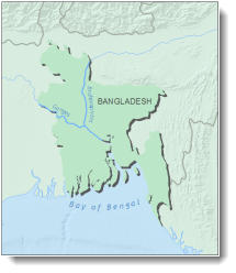
In a previous blog entry, I discussed some of the major design principles used in cartography, including figure-ground organization, which is the spontaneous separation of the figure in the foreground from an “amorphous” background. Cartographers use this design principle to help their map readers find the area of the map or page to focus on. One way to promote figure-ground organization is to use a “drop shadow” effect in which a shadow is drawn for the “figure”, giving the impression that it is raised above the ground. The way this is done in ArcMap is to use cartographic representations and the Move geometric effect.
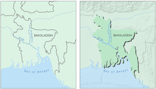
The map on the left has poor figure-ground organization. The map on the right uses a drop shadow to promote this important design principle.
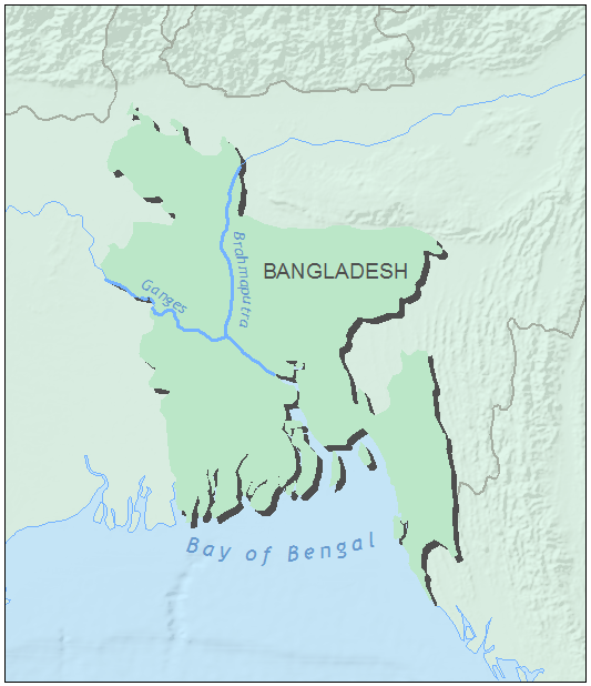
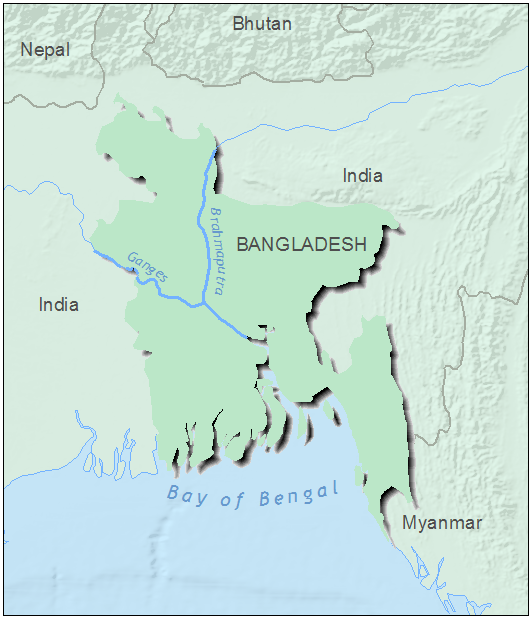
In the example below, the “figure” polygon is Bangladesh which I have emphasized with a drop shadow.
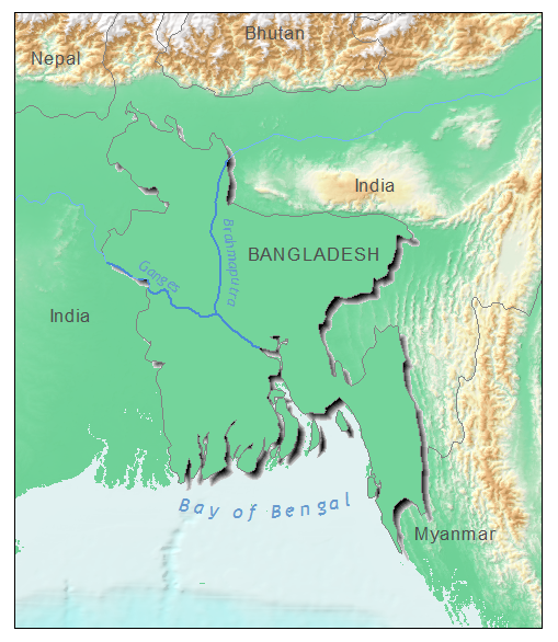
This example also shows how well this technique works when you want to provide some detail outside the area of interest – a nice alternative to simply clipping the map extent to the figure. For the map of Bangladesh, this allows you to see that the country as a whole is in a low-lying area, but its major rivers are being fed by runoff from mountains to the north and east.
In this blog entry, I explain two ways to create the drop shadow effect: the first uses a single color for the drop shadow and the second uses a gradient pattern.
Two steps are involved to create this effect:
- converting the feature class with the figure to cartographic representations, and
- applying the Move geometric effect.
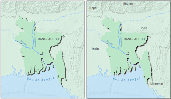
For the gradient pattern drop shadow, if you have a figure feature class with more than one polygon (as with the islands in my Bangladesh example), you may also have to make some modification using overrides to the carto reps.
Note that in order to create this effect using carto reps, you will need to convert any multipart polygons to singlepart polygons. You can use the Multipart to Singlepart tool to do this. Also, because this effect uses cartographic representations, your “figure” data must be in a geodatabase.
Single color drop shadow
Converting the feature class with the figure to cartographic representations
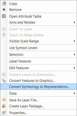
- In the table of contents, right click the feature class and click Convert Symbology to Representation.
Applying the Move geometric effect
- Right click the feature class and click Properties. On the Symbology tab, under the “Solid color pattern” heading, click the color patch and change the color to Gray 70%.
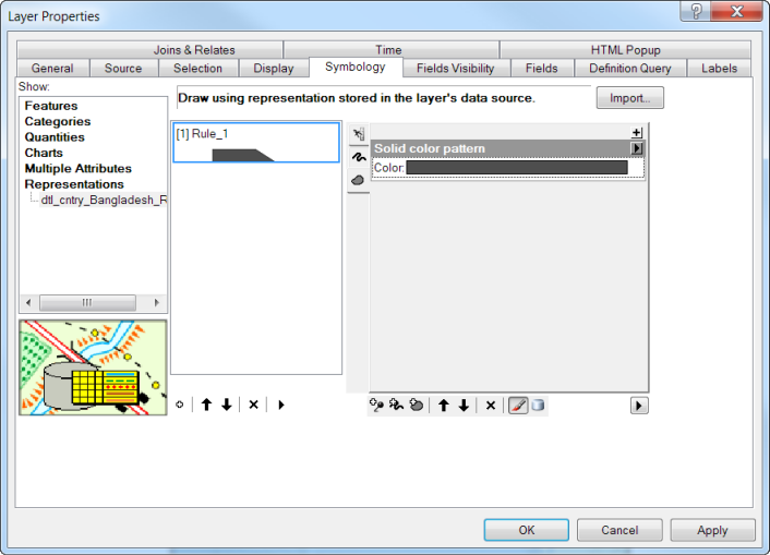
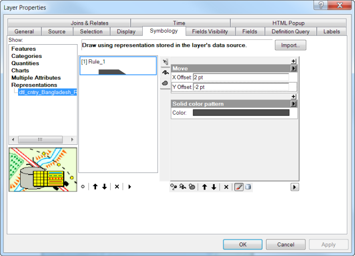
- Click the plus button at the top right to add a geometric effect and select the Move effect.

- Change the x and y offsets to 2 pts and click OK.
- In the table of contents, right click the feature class and click copy. Then right click the data frame name and click Paste Layer(s).
- For the layer that is higher in the table of contents, right click the feature class and click Properties. On the Symbology tab, shoes to show Features > Single Symbol.
- Change the color (I made the figure a slightly darker green than the background) and click OK.
The result is a simple drop shadow that helps promote the figure-ground organization.
Gradient fill drop shadow
If you want to use a gradient pattern drop shadow instead, you simply need to change the solid color pattern to a gradient pattern.
- In the table of contents, right click the layer that is drawn with cartographic representations and click Properties. On the Symbology tab, click the arrow next to the “Solid color pattern” heading and click Gradient pattern.
- Change Color 1 to Gray 10% and Color 2 to Black. Use the HSV Algorithm and the Buffer Style. Change the Intervals to 100 and the Percentage to 5, and leave the Angle at 0.
- Change the x and y offsets for the Move effect to 3 pts.
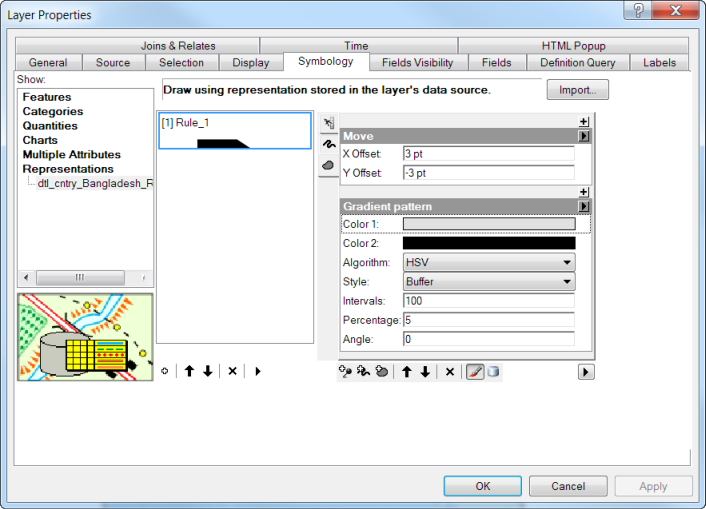
The result is a drop shadow with a softer edge.
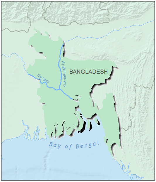
However, note that for my example, the shadow did not change for the smaller polygons that are the islands in the Bay of Bengal. This can be fixed using overrides.
Using overrides to modify the drop shadows
- In the table of contents, change the view to List by Selection. For the feature class that you converted to representations, click the first icon to make the layer selectable.
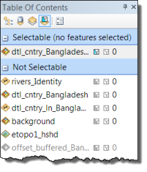
- Add the Representations toolbar to your ArcMap session by clicking Customize on the top bar menu, then Toolbars and then Representation.

- Add the Editor toolbar to your ArcMap session by clicking Customize on the top bar menu, then Toolbars and then Editor.

- Click Editor and Start editing to edit the feature class that you converted to cartographic representations.
- On the Representation toolbar, use the Select tool
 to select one of the polygons that are not displayed correctly.
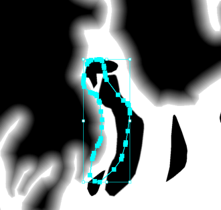
- On the Representation toolbar, click the Representation Properties tool
 to display the representation rule for the selected polygon. This will be shown to the left of the table of contents.
 - Change the Percentage value. The value to use will depend on the size of the polygon. Smaller polygons will require larger values. For the small island polygons in my example, the values ranged between 60 and 90 percent.
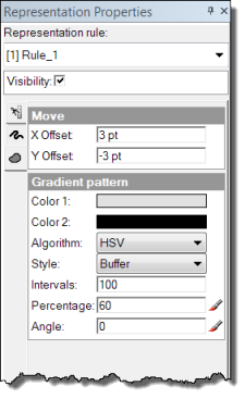
- On the editor toolbar, click Editor and Stop Editing. Save your edits.
The drop shadow should now be drawn correctly for all the singlepart polygons.

Article Discussion: