Accuracy is key to obtaining quality results when creating GIS-ready products from imagery. One field where this is especially true is drone imagery. As the name implies, Ground Control Points (GCPs) are measurements for accuracy (control) taken on the ground and recorded for use during postprocessing. The workflow involves placing a target on the ground within the planned flight area, so the drone captures multiple aerial images of it. A GPS measurement is taken at the center of the targets before or after the flight corresponding to the given target. These points can then be used after importing your imagery in Drone2Map as GCPs for correcting the spatial accuracy of output products.
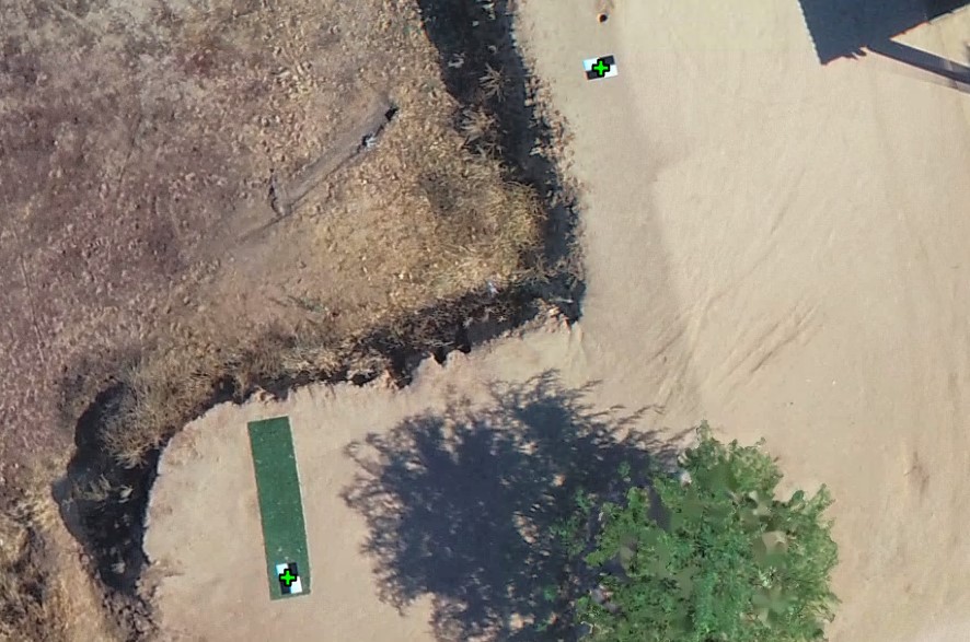
The process is simple, but the various accuracy measurements recorded and how a software handles the subsequent adjustments can become complicated.
Residual error, RMS error, and mean reprojection error
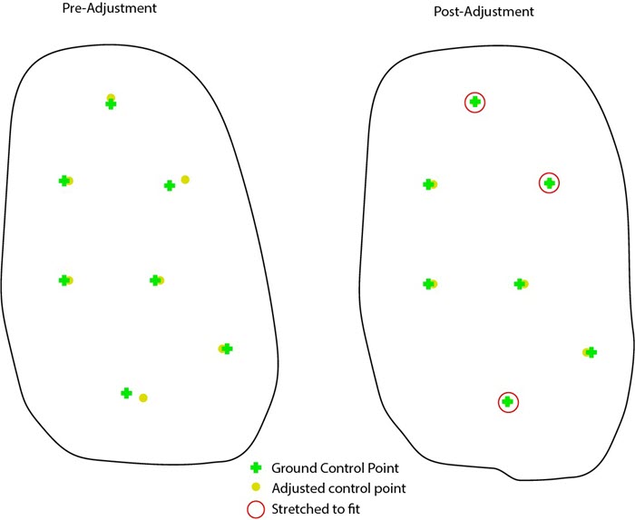
In Drone2Map, each GCP has residuals that indicate the difference in measurement between their initial position and computed position after adjustment. Residual X, Y, and Z values for each point’s ground location are calculated after the block adjustment is made. The general accuracy of how well an adjusted GCP matches that of the original GCP is summarized with an RMS error (root mean square error) of the residuals at all GCPs. This implies that the lower the RMS error, the more accurately referenced your imagery is likely to be. However, because this error is cumulative, the value can be greatly affected by even a single poorly placed GCP. Therefore, it is important that ground control point measurements be taken with care and reviewed thoroughly before being used in an adjustment.
For this reason, it is also important to consider the mean reprojection error value when evaluating a project’s accuracy. The mean reprojection error provides residual error values for the generated tie points rather than the GCPs. This tells you how accurately cameras are calibrated and how well the images are aligned to each other. A small mean reprojection error typically means that adjusted images and calibrated cameras can make rays of light from tie points perfectly intersected at their solution points.
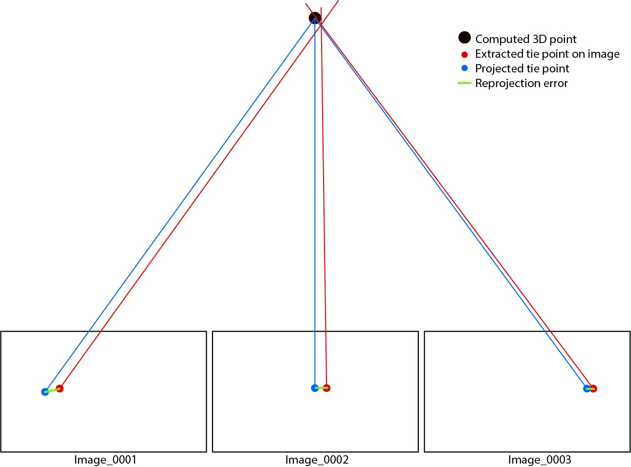
Each tie point will provide an x and y residual error value after the block adjustment is complete. These residual values reveal the difference in location between the extracted tie points and projected tie points and are calculated as the mean reprojection error.
It is important to note that tie points are not solution points. Tie points refer to the automatically extracted and matched feature points or measured points on images. For an adjusted project, you may see a huge number of solution points. Each solution point has a corresponding tie point on an image. The 3D coordinates of solution points are computed using the tie points’ image coordinates and image orientation.
Adjustment methods in Drone2Map
There are two kinds of adjustments used in Drone2Map. The first is used by default in the software and is called the free network adjustment without GCPs. This adjustment relies purely on the matched feature points (tie points) to refine image orientation and camera parameters. After an adjustment is run, the 3D solution points are projected back onto images using optimized image orientation and camera parameters. We call these projected tie points. By comparing the difference between projected tie points and the extracted and matched tie points, we can compute the mean reprojection error. This mean reprojection error can be used as quality control for the free network adjustment.
The second type of adjustment incorporates your GCPs to enhance the accuracy of the project. Tie points are manually created when importing and linking the GCPs to the imagery. Another adjustment is then carried out using the tie points from the free network adjustment and ones from GCPs to georeference the whole project into an absolute coordinate system. By comparing the difference between 3D coordinates of GCPs’ solution points computed in adjustment and GCPs’ initial 3D coordinates, you can compute the RMS error.
Getting different accuracy results in other software
To understand why accuracy differs between software, you need to look at how the calculations are applied.
RMS error of ground control points
To keep the software user friendly, Drone2map and many other photogrammetry processing programs initially import GCPs with a default horizontal and vertical accuracy value, if the values in the fields are blank. The accuracy of your GCPs may not be as accurate as that default value though. If this is determined to be the case during the processing, then the output products may be stretched to achieve the best fit between your GCPs. This tends to skew the RMS error value to appear more accurate than in reality. Ideally, these default values should only really be used when you are adding GCPs from the Map instead of importing collected points.
An RMS error value is the standard deviation of the residuals. It tells you how concentrated data is around the line of best fit. The formula for calculating this is as follows:
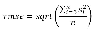
Where:
Σ = sigma (summation)
Si = samples
n = sample size
Any GCP should give three residuals in dX, dY, and dZ after adjustment. So RMS error values in X, Y, and Z can then be computed from the residuals from all GCPs.
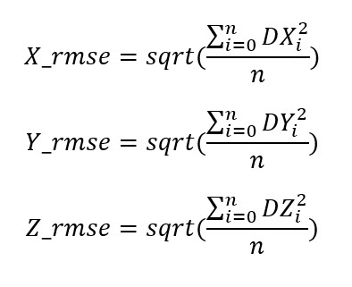
Where:
DXi, DYi, and DZi = residuals at GCP i
n = sample size
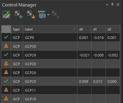
For many programs, even if error is intentionally introduced to the processing, the RMS error accuracy values may not change. If you take the project and modify one of the control points with these default values to instead be 1 meter horizontally away from its initial position without changing that default accuracy value, you can then compare the results to the original project to test if the value changes.
If the RMS error value does change significantly, the accuracy is being correctly honored. More than likely, though, you will see that even when you introduce error into the control points location, the RMS error value calculated for that point is the same. However, this is not the case with Drone2Map.
How accuracy works in Drone2Map
In Drone2Map, the false accuracy is no longer honored, and the manually edited GCP is marked with a large residual of around 1 meter after the bundle adjustment.
Mean reprojection error
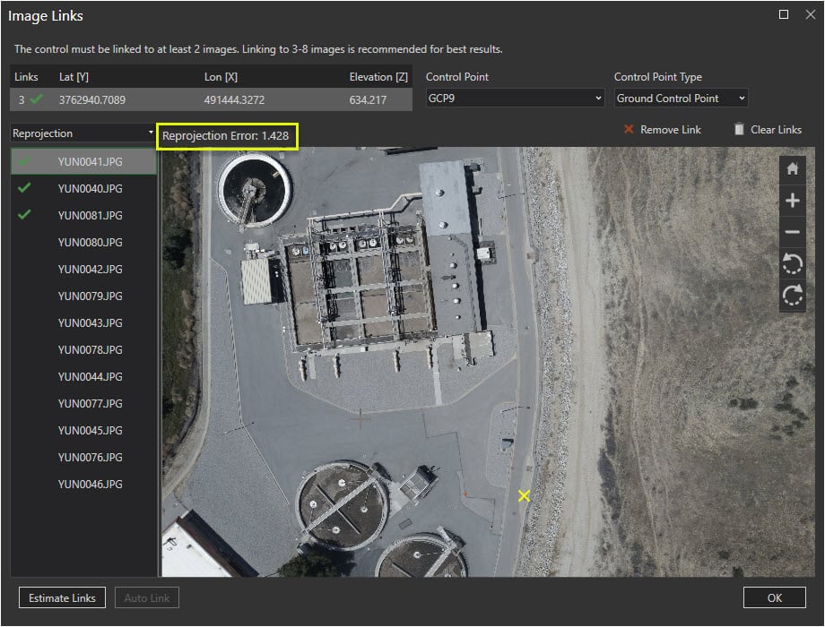
A tie point should give two residuals for x and y after any adjustment. These residuals tell the difference on the image between the extracted tie point and projected tie point. Drone2Map computes mean reprojection error as the following:

Where:
dxi and dyi = residual at tie point i
All tie points are equally weighted in Equation 1.
If tie points used in adjustment are SIFT points or other feature points which have the scale in feature properties, there is a different equation for computing mean reprojection error as the following:

Where:
wi = the scale of feature point i
The magnitude of wi is usually larger than 1.
If you were to compare the mean reprojection error for the same project between the two programs, you will find that mre from equation 1 is larger than the mre from equation 2, which is the case in some drone imagery processing software. This is due to weighting and does not mean the former adjustment’s intra accuracy is worse. The same weighting could be applied in Drone2Map and you would receive very similar result. However, the intent with Drone2Map is to provide the most accurate view of your adjustments which is why we opted to avoid applying the weighting. This allows you to more clearly see areas of your project that may need improved collection or refinement.
Summary
Understanding the concepts and methods used to implement your control and image accuracy in Drone2Map is key to obtaining the best products possible. It is important to consider not only RMS error values when evaluating accuracy but also the mean reprojection error. With this knowledge, you can troubleshoot flight areas that need improvement and derive more accurate products.


Article Discussion: