By Aileen Buckley, Mapping Center Lead
In a previous blog entry, I discussed some of the major design principles used in cartography, including figure-ground organization, which is the spontaneous separation of the figure in the foreground from an “amorphous” background. Cartographers use this design principle to help their map readers find the area of the map or page to focus on. One way to promote figure-ground organization is to use a “feathering” effect in which the edges of the map are softened and appear to blend into the background. The way this is done in ArcMap is to use a buffered vignette and the advanced drawing setting for transparency. Note that, as described, this method requires an ArcEditor or ArcInfo level license; however, a user comment to this blog post describes how you can achieve this effect with an ArcView level license as well.
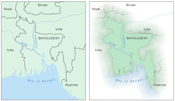
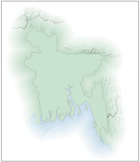
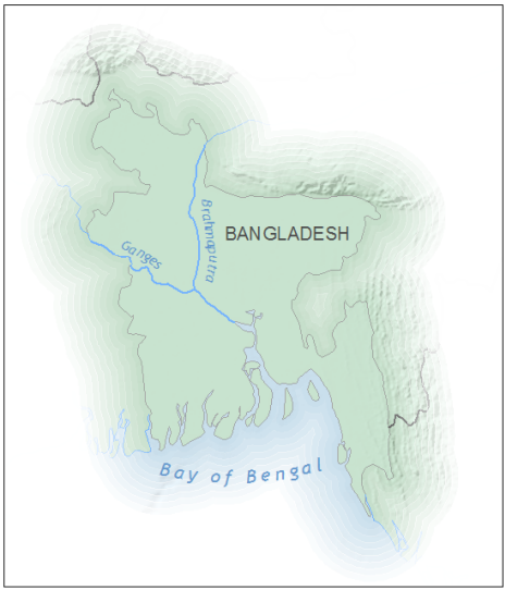
The map on the left has poor figure-ground organization. The map on the right uses feathering to promote this important design principle.
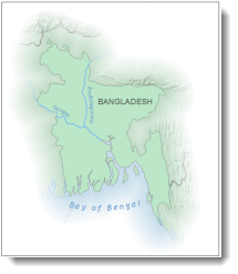
In the example below, the “figure” polygon is Bangladesh which I have emphasized with a feathering effect.
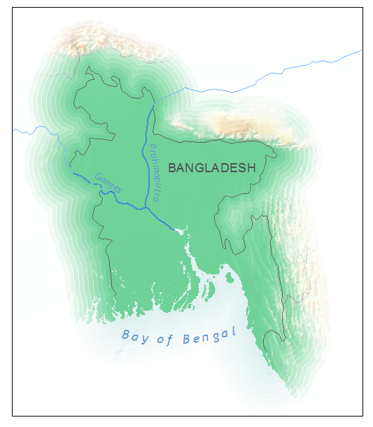
This example also shows how well this technique works when you want to provide some detail outside the area of interest – a nice alternative to simply clipping the map extent to the figure. For the map of Bangladesh, this allows you to see that the country as a whole is in a low-lying area, but its major rivers are being fed by runoff from mountains to the north and east.
Four steps are involved to create this effect:
- creating buffers for the vignette,
- adding a “universe polygon” to the buffer vignette feature class,
- adding and calculating the transparency attribute, and
- symbolizing the buffers using transparency.
Creating buffers for the vignette
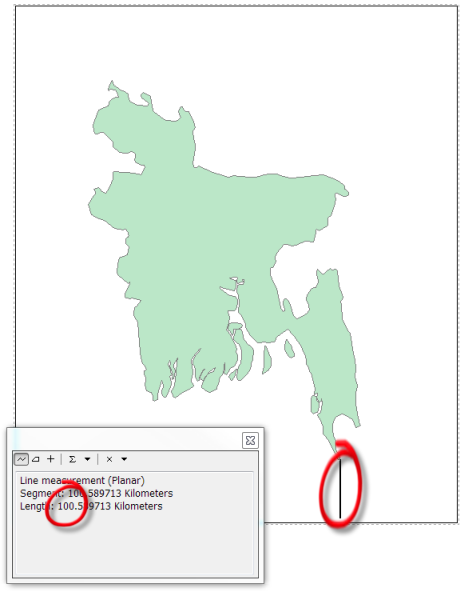
To get an initial idea how far you want the “feathering” to extend, use the Measure tool. For my map, I decided that I wanted the feathering effect to end a small distance from the furthest extent of the feathering to the edge of the page – that distance is about 100 kilometers.
TIP: You can also use the Multiple Ring Buffer tool in the Analysis toolbox. Using the Buffer Wizard instead is a little faster, especially if you want to experiment with the number of buffers and the distances.
To add the Buffer Wizard tool to your ArcMap session, click Customize on the top bar menu and then Customize Mode. In the “Show commands containing:” area, type “Buffer Wizard”. Click on the Buffer Wizard tool then drag and drop the tool onto any toolbar displayed in the ArcMap window. Click on the tool to open it.
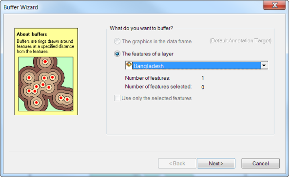
- On the first page of the wizard select the feature class that contains a polygon for the area that you want to be the “figure”.
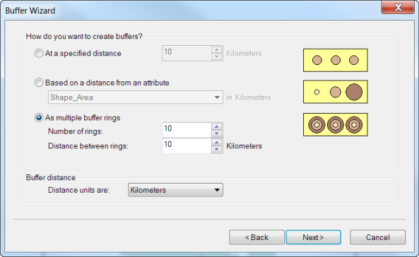
- On the second page, choose the third option to create buffers “As multiple rings”, and set the number of rings and distance between rings. Note that the more rings you add, the smoother the effect but more rings will also slow down the drawing time. Generally, between 10-20 buffers is sufficient, depending on the total distance you want to use for the “feathering”
.
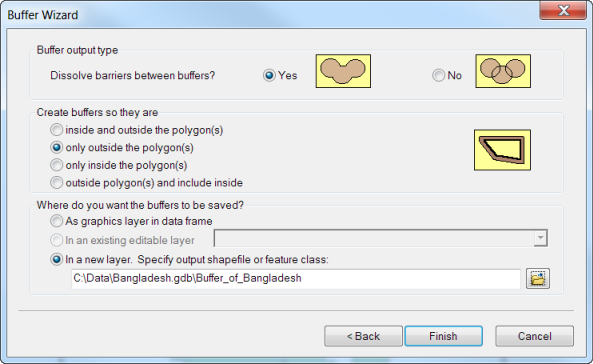
- On the third page, choose the options to:
- dissolve buffers between barriers,
- create buffers so they are only outside the polygon,
- save the buffers in a new layer, and
- specify the name and location of this new layer.
Adding a “universe polygon” to the buffer vignette feature class
Notice that you can see outside the extent of the last buffer. What you need to do is add a polygon to the outside of the buffers – we’ll call this the “universe polygon”. There are many ways that you can do this – I find that this is one of the easiest:
- In Layout view, double click the data frame to “focus” it.
- Using the New Rectangle tool on the Draw toolbar, draw a graphic that fills the extent of the page.
- Switch to Data view and make the rectangle a little larger than the page extent using the handles to pull box out on opposite corners.
- Switch back to Layout view.
- Right click the data frame in the table of contents and click Convert Graphics to Features.
- Name the output feature class MapExtent and check the option to “Automatically delete graphic after conversion”.
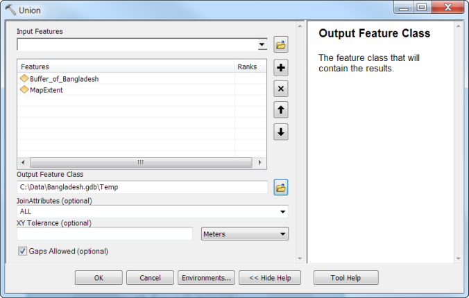
- Use the Union tool in the Overlay toolset of the Analysis Tools toolbox with the buffer feature class and MapExtent as the input features, and name the output feature class Temp.
- To remove the inner polygon, use the Erase tool in the Overlay toolset of the Analysis Tools toolbox with Temp as the Input Features and the polygon for the area that you want to be the “figure” (in my case, Bangladesh) as the Erase Features, and name the output feature class FeatheringEffect.
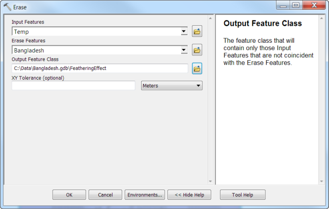
The result will include the buffers and the universe polygon but not the inside polygon.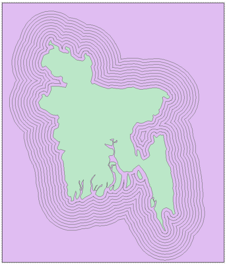
- Remove Temp from the table of contents.
Adding and calculating the transparency attribute
Now you need to add an attribute and calculate the transparency values.
- Right-click the FeatheringEffect layer in the Table of Contents and click Open Attribute Table.
- Click the Table Options button and click Add Field.
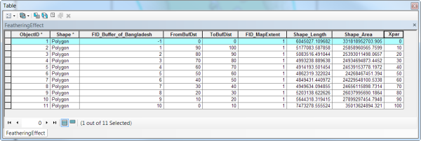
- Name the field “Xpar” which is an abbreviation for “transparency”.
- Click the Type dropdown arrow and change the field type to Long Integer.
- Click OK.
- Right-click the Xpar field heading and click Field Calculator.
- Enter the following:
((100 * [FromBufDst])/the largest FromBufDst value)
This calculate statement will calculate transparency values that are a function of the distance so that the buffers farther away are less transparent. Click OK. - Click on the box at the very left of the first record in the table (the one with an FID of -1) to select the “universe polygon”. Use the Field Calculator to calculate the Xpar value as 0.
Symbolizing the buffers
- Right-click the FeatheringEffect layer in the table of contents and click Properties.
- Click the Symbology tab.
- In the “Show:” area, click Features > Single Symbol.
- Click the Symbol patch to change the symbol. Change the Fill Color to White and the Outline to No Color.
- Click OK to close the Symbol Selector dialog.
- Click the Advanced button next to the symbol patch and click Transparency.
- Select Xpar as the field that you will use to vary the transparency of the features.
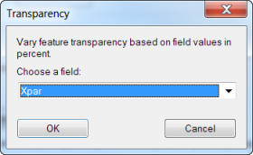
- Click OK.
If you want to add any other features, be sure to place them under the FeatheringEffect layer in the table of contents. If you have text that falls within the feathering area and you also want it to be affected by the feathering, convert it to annotation and place it under the FeatheringEffect layer as well (otherwise the text will draw over all the layers including the FeatheringEffect layer).
Now all that is left to do is symbolize the layer. The result is a subtle fading out to the background.

Article Discussion: