The utility network was designed to allow a utility company to model different types of utilities in a single, connected network. While these utilities have historically been modeled as separate networks, we wanted to allow customers to model them as a single network to enable seamless analysis between these datasets. While there are many benefits to modeling assets in a single, shared network, this approach also imposes constraints on how you use and manage your data.
The purpose of this article is to inform you about the key talking points to help you make the right decision for your organization. You will find a summary of these talking points at the end of the article.
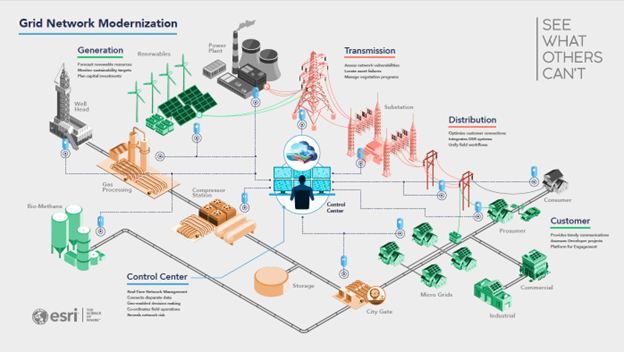
Below you can see an example of the types of data an electric utility maintains. In most cases, the generation, transmission, and distribution data in the organization are managed as separate datasets by separate departments within the organization. While it is possible to model these as a single, interconnected network, many organizations may choose to continue to model them as separate networks for organizational or even regulatory reasons.
Below you can find examples of some of the different water utilities that an organization may be responsible for. These utilities can be modeled as a single, connected network or as separate interconnected networks. This article talks through the considerations an organization makes to determine the approach that works best for their needs.

In this article we will discuss some of the pros and cons of each approach so you can determine the best approach for your organization’s data and requirements.
Consider the following example scenarios:
- Combining bulk power and distribution networks into a single connected network.
- Identifying shared poles between a utility’s electric and communication assets.
- Identifying where the stormwater system could cause a combined sewer overflow (CSO) event.
- Tracking the lifecycle of water from the potable water system to a reclaimed water system.
Modeling multiple domains in a single network makes the analysis seamless for many requirements that customers have had for years. It is still possible to solve these problems using separate utility networks, but this requires additional steps to propagate the analysis between multiple networks and consolidate the results. If this analysis only happens several times a year, this may be a tolerable workaround. But if this is something that needs to happen daily then the burden may become too great.
Modeling all your data in a single network sounds appealing; however, it does come with limitations. When features are modeled as part of a single network, viewing and editing privileges are shared for all the data in the network. If you want to have separate permissions for each domain in your network, you will need to model them as separate network. While you can attempt to control this through client-side access controls, users can bypass these controls by directly accessing the services through a different client.
Similarly, as administrative privileges are shared across the entire network, a single schema change affects all users of that network, and not just the department whose schema is changing. This means that when you need to turn off the services to perform network maintenance, it will affect all users of that network.
Customers with datasets in many different regions may also choose to maintain separate networks in different regions. Some of the common requirements for this decision are:
- Regions requiring different coordinate systems
- Differing schemas, workflows, or configurations for each region
- Unique or conflicting regulatory requirements for each region
- A need to maintain separate networks for different operating companies
- Inability to support each region through a single, centralized architecture
Now that we’ve discussed some of the pros and cons of modeling using a single network, let’s discuss the pros and cons of using multiple networks.
Maintaining multiple networks

The most immediate benefit of using multiple networks is that they can be edited and managed separately. This is because the separate networks must be in separate feature services and different feature datasets. Because all features in a feature dataset share a coordinate system, having different feature datasets for each network allows them to have different coordinate systems.
A feature service can only contain a single utility network, because of this each of the utility networks will have its own dedicated feature service. This makes it possible to allow editors from different departments to have editing permissions on their department’s network while only being able to view the network of another department.
Another benefit of having separate feature services for each network is that it allows you to perform schema changes on each network separately. This means that when you need to schedule downtime to make changes to one network, users can continue to use the services for other networks.
In additional to the business requirements an organization also need to consider the architectural impacts of their decision.
Architectural impacts
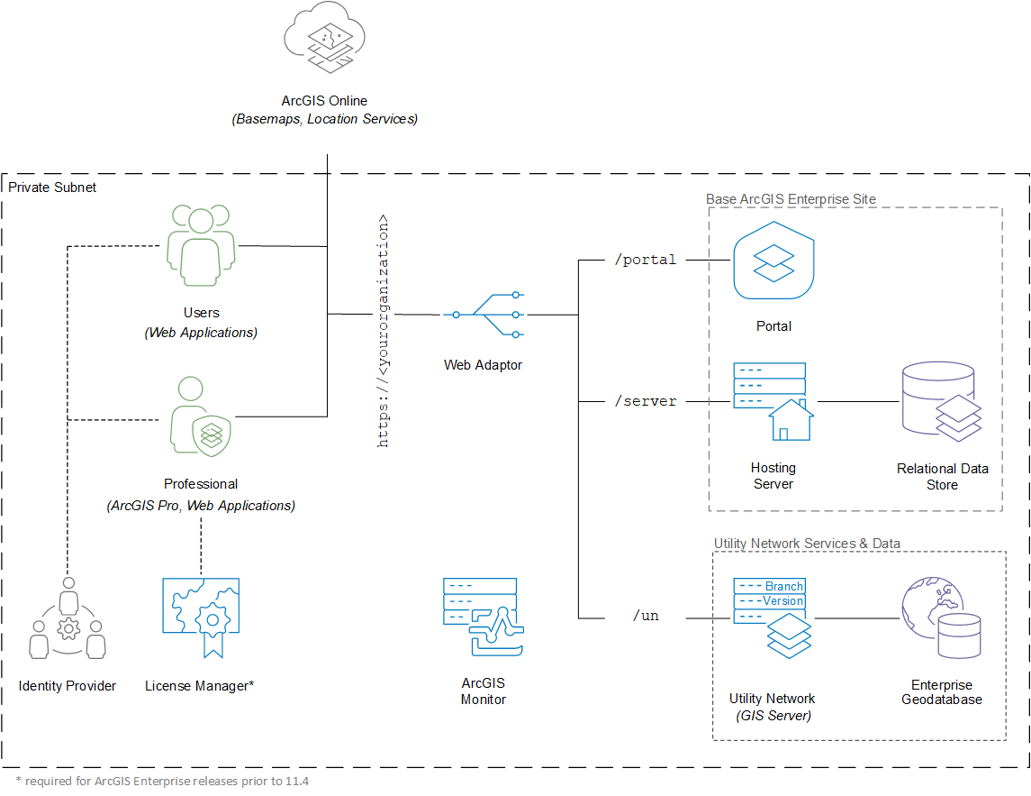
If you designed a system to use one utility network, and later decided to use multiple utility networks, this decision alone should not significantly impact the architecture or hardware requirements of your deployment. You could continue to use the same database to host multiple utility networks, publish the multiple services to the same servers, and then continue managing the data using the same portal that you had originally designed. However, if you are in a situation where you need to maintain separate hardware for different regions, then each region would need to have its own site with its own dedicated geodatabase that contains the network data for that region.
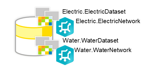
Just as a utility network can contain multiple domains, a single geodatabase can contain multiple utility networks. When a geodatabase contains multiple utility networks it is recommended that they be in separate database schemas. The reason for this is that all utility networks have a common set of Structure tables. Placing them in separate schemas prevents the structure tables from having conflicting names and allows you to easily differentiate the structure features in a water network from the structure features in an electric network.
There is no strict need to separate utility networks into different databases or database servers. Some customers may choose to do so if they wish to have separate, dedicated resources for each network. However, when features are separated into different geodatabases you lose access to certain geodatabase capabilities that are limited to datasets in a single geodatabase like attribute rules, relationship classes, etc.
Another question customers ask is whether multiple utility networks can share the same ArcGIS Server machines or whether each network requires its own dedicated set of machines. The answer to this question is the same as the question of whether a utility network should have a dedicated database server. Multiple utility networks can share the same set of server resources, but some customers may choose to have separate, dedicated resources for organizational reasons, or so they can adjust the resources for each network separately. The same may also be done to minimize the impact of network latency at the server tier (between the Geodatabase and GIS Server) and the client tier (between ArcGIS Pro, web clients, and mobile clients) on system performance.
You can learn more at the Deployment patterns (Network Information Management System) page in the ArcGIS Architecture Center as well as refer to the Test study gallery for examples of different architectures.
Conclusion
Hopefully you now have a better understanding of the basics as to why some organizations choose to separate or combine their network datasets in a utility network. As you can see there is no single, correct answer. You must weigh the pros and cons of each option to determine the path that is most appropriate for your organization.
Below you will find a table that summarizes the requirements discussed in this article and whether they favor a single network or multiple networks.
| Requirement | Type | Single Network | Multiple Networks |
| Different Spatial References | Business | X | |
| Multi-domain analysis | Business | X | |
| Same schema, rules, workflows, etc | Business | X | |
| Shared Structure Features | Business | X | |
| Administrative Considerations | Technical | X | |
| Security Considerations | Technical | X | |
| Regional Data Centers | Technical | X | |
| Shared Data Centers | Technical | X |
You should now have enough information to start the conversation about what approach is best for your organization, but if you find yourself having more technical questions you should reach out to Esri or a business partner to help answer your questions and get you started down the right path.
You can also find a selection of resources to help you make architectural decisions at the ArcGIS Architecture Center. When looking for architectural resources related to the ArcGIS Utility Network you will want to start by looking at the Network Information Management reference architecture.

Commenting is not enabled for this article.