
Projection-on-the-Fly Simplifies Data Integration
Visualizing Earth from Space Improves Local GIS
By John Schmidt, President, NCAD CorporationGeodesy: The determination of the size and shape of the Earth and the exact positions of points on its surface.
 To solve common GIS problems, such as merging adjacent planar coordinate systems--most notably at state boundaries, we start with geodesy, visualizing Earth as an object in space. Among astrophysical scientists, there is global consensus, based on observations of continual expansion, that the universe began as a Big Bang. Our Milky Way is one of hundreds of billions of expanding galaxies in the universe, and within the Milky Way, there are billions of stars--one of which, our Sun, hosts planet Earth. Each of us is a product of Earth, and we are increasingly aware of our responsibility to manage our planet. As managers, we must use metrics for space and time. Time is the partition of a cycle. The rotational cycle of Earth relative to Sun is divided by two, then twelves and fives, defining hours, minutes, and seconds. The complete cycle, one day, is the unit partitioning the orbital cycle of Earth around the Sun, our year. The astrophysical basis and singular standard for time is globally accepted. But our use of standard metrics for space has not yet reached this consensus.
A viewpoint from outside the solar system allows us to visualize Earth as nearly a sphere, more nearly an ellipsoid. Too irregular to model in perfect detail, Earth is thus modeled as either
(1) A solid object in three-dimensional Cartesian space
(2) A surface of an ellipsoid
 (1) A Solid Object in Three-Dimensional Space--Three-dimensional space, containing solid Earth, is defined as a spinning, infinite volume beginning at Earth's center of mass (CoM). This origin (0,0,0) may be inferred by observation of the moon and other satellites orbiting Earth. The z dimension is based on the axis of rotation of Earth, commonly modeled on every rotating globe, and passes through Earth's CoM. The CoM is also the intersection of the z axis with the equatorial plane, orthogonal to the z axis, and intersecting the surface of Earth at the equator. In this equatorial plane are the x and y axes of the three-dimensional, Earth-centered (geocentric), volumetric, Cartesian space.
Above right: Three-dimensional space is defined from a point at the Earth's center of mass (CoM). The Z axis passes through the CoM, at the intersection with the equatorial plane, in which occur the x and y axes of the three-dimensional, geocentric, Cartesian space. This space also contains the ellipsoid surface.
(2) A Surface of an Ellipsoid--As a surface, Earth is best modeled by an ellipsoid centered at the same CoM origin, defined by its semimajor axis and degree of flattening. The distance from CoM to equator (semimajor axis) is 6,378,137 meters; the distance to the poles is shorter by 22 kilometers. Positions are specified on the ellipsoid in degrees of rotation from two reference planes. Latitude is the angular measurement from the equator; longitude is the angular measurement from the prime meridian.
The standard geocentric Cartesian spatial model is the International Terrestrial Reference Frame maintained by the International Earth Rotation Service (IERS) (www.iers.org/iers/products/itrf) based in France and updated yearly. The standard surface model, GRS 80, was adopted in 1979 by the International Association of Geodesy (www.iag-aig.org/).
Together, these models comprise the World Geodetic System, as in WGS 84, which is declared by the United States Department of Defense to be the definitive coordinate system for Earth modeling consistent with the Global Positioning System. Within WGS 84, conversion between the two standard coordinate systems, "geocentric" and "geographic," is precisely direct, involving no projection and no distortion (see ftp://maia.usno.navy.mil/conventions/chapter3/geod.f).
A Standard for Space
So, for space, just as for time, we have an astrophysical basis for a singular, globally consistent standard, diligently maintained by accepted, international organizations, to use worldwide for basemaps supporting GIS and ad hoc projects. Then why is use of this global standard not so universal? In an (astrophysical) word, inertia. Because this coordinate system is relatively new, as are tools for reliably measuring within this system, common practice is to use some other, less perfect, coordinate system for the basemap. So the current legacy status around the globe is inconsistent use of local, planar coordinate systems, most troublesome in areas straddling State Plane coordinate systems such as regions around Columbus and Cincinnati, Ohio.
The Convergence of Three State Plane Zones
In Cincinnati the regional planning agency, especially for transportation, is the Ohio-Kentucky-Indiana Regional Council of Governments (OKI). Three incongruous State Plane Zones converge within the circle freeway I-275. Currently under way are three studies evaluating and planning transportation crossing the state boundary between Ohio and Kentucky, namely the Ohio River. The I-71 and I-75 freeways merge at the Ohio River, through northern Kentucky, providing access to the Cincinnati Northern Kentucky International Airport eight miles into Kentucky on the circle freeway. The best data on the Ohio side is maintained locally in the Cincinnati Area Geographic Information System (CAGIS) managed by Shaoli Huang. Across the river, Tom East of the PlaNet GIS Partnership focuses on northern Kentucky. Until now, data from both sources could not be enjoyed in a single map view without the pain of conversion. According to East, "Every need for conversion requires good communication between at least two people, and often more than one trial, consuming valuable GIS resources."
ArcGIS 8.1
But now with ArcGIS 8.1, users and administrators can add data layers, based on dissimilar coordinate systems, within the same data frame. When a layer is added to a data frame, ArcGIS 8.1 reads the layer's PRJ file and automatically projects or unprojects the feature coordinates to register with the coordinate characteristics of the data frame. This is termed projection on-the-fly (POF). The implications of this new magic are profound, as we will finally discuss.
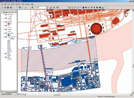
This ArcMap screen capture demonstates State Plane integration using POF.
No conversions were performed on the data.
But first, let's view a demonstration of State Plane integration. The ArcMap composition in the screen capture above indicates a data frame named NAD 83 UTM-17N including blue layers based on NAD83 State Plane Kentucky North HARN from the PlaNet GIS Partnership, mixed with red layers based on NAD83 State Plane Ohio South from CAGIS. No conversions were performed on the data.
With ArcGIS 8.1, we enjoy more freedom from the complex matters behind coordinate systems. Using ArcCatalog, each layer is right-clicked to specify its coordinate system, producing an ASCII file with a PRJ extension, having the same primary file name as the data name. This projection file may specify geographic (surface) or projected (planar) map data coordinates. In the ArcMap table of contents, data layers are added in a data frame (root folder). Multiple data frames may occur, only one of which is active at a time, similar to an ArcView GIS 3.x View window. Also similar to the View window, a property of each data frame is the coordinate system configuration, defining the view without changing the data. In ArcMap, this property is automatically set by the first layer added to the frame but may be changed at any time.
An increasingly significant tool for data collection is GPS. Currently, those who collect this data are often asked to submit the data in the form of the current GIS project coordinate system, commonly, a two-dimensional State Plane projection, where z is orthogonal to the plane. Thus, the data provider, or the GIS administrator, is encumbered by the requirement of making a conversion; and, by definition, the GIS is based on a distorted model of reality.
With ArcGIS 8.1, the pain of conversion is made practically obsolete. More importantly, the opportunity arises for building a spatially accurate, three-dimensional model of reality based on the best available data. Data may be provided based on any coordinate system, including GPS (WGS 84), and (POF) be transparently integrated in ArcMap using a display coordinate system to meet immediate practical needs. Any reports or printed maps may be produced by simply changing the properties of the data frame prior to printing. By reducing the time spent on geospatial integrations, ArcGIS 8.1 enables more efficient and more accurate models for all GIS users.
For more information, contact John Schmidt, NCAD (tel.: 859-727-9999, e-mail: john@ncad.net, Web: www.ncad.net).