ArcUser Online
Editor's note: Mars, a glowing red eye in the night sky, has fired the imagination of people since ancient times. More recently, Mars has been the favored destination of space travelers and the home base for invading extraterrestrials in science fiction novels. However, during the last 40 years the National Aeronautics and Space Administration (NASA) has been replacing Mars science fiction with knowledge of this intriguing planetary neighbor. The Mars Exploration Rover (MER) mission is part of NASA's quest to explore the planet using both orbiting spacecraft and robots. This mission has built on the success NASA experienced with the first rover, Sojourner, during the Mars Pathfinder mission in 1997. The MER mission's rovers are the next generation of robotic geologists. Early in the summer of 2003, the twin rovers Spirit and Opportunity left earth aboard separate Delta II rockets bound for Mars. Both rovers were successfully landed, each on opposite sides of Mars in early January 2004 and began carrying out their mission to search for indications of the presence of water on Mars. Deciding where to land the rovers was critical to the success of the mission. The sites chosen had to ensure the rovers' safety while placing the rovers in locations that were geologically promising. The landing sites chosen were Gusev crater, a giant impact crater that might have been the location of a lake, and Meridiani Planum, an area of mineral deposits (i.e., hematite) that suggests the presence of water. These sites have proved propitious indeed. On March 2, 2004, mission scientists hit pay dirt. On that day, Opportunity examined a rock dubbed "El Capitan," that exhibited changes in texture and chemistry that indicated liquid water flowed through these rocks. In this special section, Trent Hare of the United States Geological Survey's Astrogeology team, has provided a tutorial that lets readers map both rover landing sites in ArcMap using digital elevation models (DEMs) created with the recently released Mars Orbiter Laser Altimeter (MOLA) data and other data sources. With the successful landing of the two Mars Exploration Rovers Spirit and Opportunity in January 2004, Mars has once again commanded the attention of cartographers around the world. Along with the images sent home from the rovers, the planetary community is also being overrun by a wealth of Mars satellite imagery and data from other missions. There are three active satellites currently circling Mars. Mars Global Surveyor (MGS) and Mars Odyssey (MO) are funded by the National Aeronautics and Space Administration (NASA). The third satellite, Mars Express, was launched by the European Space Agency. Another, the Mars Reconnaissance Orbiter, is scheduled for launch in 2005. What does this mean to the average planetary cartographer? Put succinctly, hundreds of data sources are now available and require tools that can combine and manipulate them in one interface.
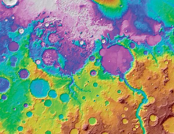
In this exercise, we will create basemaps that will show the landing sites for the two Mars rovers using the MGS Mars Orbiter Laser Altimeter (MOLA) and Mars Obiter Camera (MOC) datasets and the MO Thermal Emission Imaging System (THEMIS) datasets. The MOLA instrument, built by the Laser Remote Sensing Branch of NASA, collected more than 600 million topographic measurements between 1999 and 2001. These measurements were further adjusted for consistency and then used to create digital elevation models (DEMs). These DEMs have revolutionized Mars mapping. They have provided a marvelously accurate definition of the shape and location of features on Mars to such a degree that it has been said we now have a better understanding of the shape of Mars than of earth. (This can cleverly be said because much of the Earth's surface is shrouded by its oceans.) MOC and THEMIS are two very different scanning cameras or imaging systems. The MOC camera was designed and is currently being operated by Malin Space Science Systems (MSSS), a San Diego, California, company that designs, develops, and operates instruments that fly on robotic spacecraft. THEMIS, which contains a 10-band infrared imager designed by Raytheon/Hughes and a five-band visible imager designed by MSSS, was initiated and is currently being run by Arizona State University (ASU).
The latest near-global MOLA DEM was released in May 2003 at approximately 463 meters/pixel (1/128 degrees per pixel). It covers latitudes from 88� North to 88� South and the full 360� longitude range. As a single image, this map would be approximately 2 GB in size, so it has been divided into 16 tiles for ease of downloading and use. Each tile is stored as a separate image file with a detached Planetary Data System (PDS) label and an .lbl file extension. The tiles can be used alone or reassembled to make a map that nearly covers the planet. Each tile covers 44 degrees in latitude and 90 degrees in longitude. The maps are in an equidistant cylindrical projection with a central latitude (standard_parallel_1) defined at 0� and a central meridian at 180�. Continued on page 2 |