ArcUser Online
Most pipeline alignment tasks involve linking the conduit from an origin point to a destination point. In some applications, more than one origin and destination may be required for the same alignment. Between the origin and destination points, decision makers are always confronted with numerous and a sometimes seemingly infinite number of potential corridors from which to choose. Pipeline alignments have been designed using many methods ranging from filling out simple and subjective forms to employing sophisticated GIS tools. The ArcGIS Network Analyst extension can be used for performing spatial analysis on linear networks. Node-to-node routing, one of the types of analysis that can be performed using Network Analyst, minimizes an objective function (i.e., define the shortest route). Having said that, is producing one "best" route the most desirable result for all applications? Depending on the network, a significant number of potential routes may be possible. Depending on the specific network problem being considered, a single best solution may not be the most feasible or useful. For example, the third best route from a cost perspective may be the best when considered from a maintenance or environmental perspective. Decision makers often like to consider multiple options before coming to a final decision on the selected route, especially for significant and large diameter pipelines. For these reasons, modelers typically generate more than just the default "best" route. Selecting more than one default route using ArcGIS Network Analyst can be done both manually and programmatically.
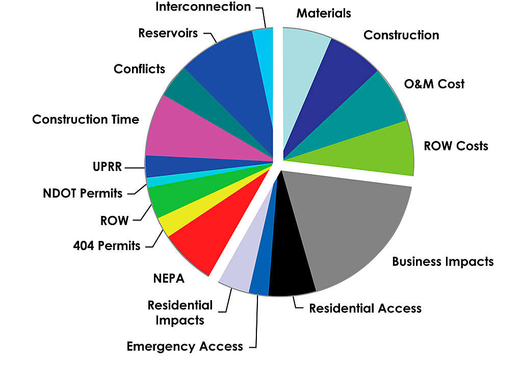
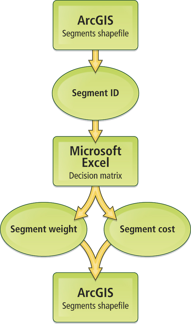
This article summarizes the use of ArcObjects and Visual Basic for Applications (VBA) to develop a custom application for pipeline alignment optimization that can identify a number of potential routes and list and rank these routes for further analysis in an automated fashion. The application extracts project-specific information, including segment weights and costs from a Microsoft Excel spreadsheet, and imports them as attributes to a pipe network feature class composed of individual pipe segments. The application loops through the potential corridors to list a predetermined number of potential routes. A feature class listing these corridors is generated and displayed. The application then exports the output back to Microsoft Excel and ranks the corridors according to their total weight (summation of weights for the comprising segments) and costs and generates a graph illustrating all the generated corridors in a triaxial chart for quick analysis of the potential routes. This application uses a pipe segments feature class in which the segment IDs are stored as integers in a field named SgID. It also uses a decision matrix, a two-dimensional table listing all segments available between origin and destination points and their scores for each criteria and subcriteria included in the analysis. The decision matrix is created in Microsoft Excel. Decision makers and stakeholders use Excel when developing project priorities, defining project design criteria, assigning relative weights to criterion, and assigning a score for each segment for each criterion. This is a preprocessing tool that aggregates all factors into two numbers—weight and cost. Weight combines all segment weighted scores on all criteria, while cost combines the associated costs for each segment. Engineering, environmental, and socio-economic factors are considered in the decision matrix. Each segment is given a score on each of these factors along with the relative weights between these criteria. The weighted score for both weight and cost is calculated for each segment. The lower the value assigned to the segment, the more desirable the segment would be for the pipeline corridor. Engineering considerations include land uses, terrain, materials, constructability, right-of-way acquisition, crossings and conflicts, soils, geology, length, and operation and maintenance. Environmental considerations include land use, visual and physical impacts, National Environmental Policy Act (NEPA), permits (for departments of transportation or local and regional agencies, or for Section 404 [permits issued pursuant to Section 404 of the Clean Water Act, which regulates the discharge of dredged, excavated, or fill material in wetlands, streams, rivers, and other U.S. waters]), and site conditions.
Socioeconomic considerations include business and residential impacts, agency considerations, and construction time. Once the pipe network is identified and the decision matrix is populated with the relative scores and weights for all the segments and criteria, the application is ready for the analysis. The analysis process consists of three steps:
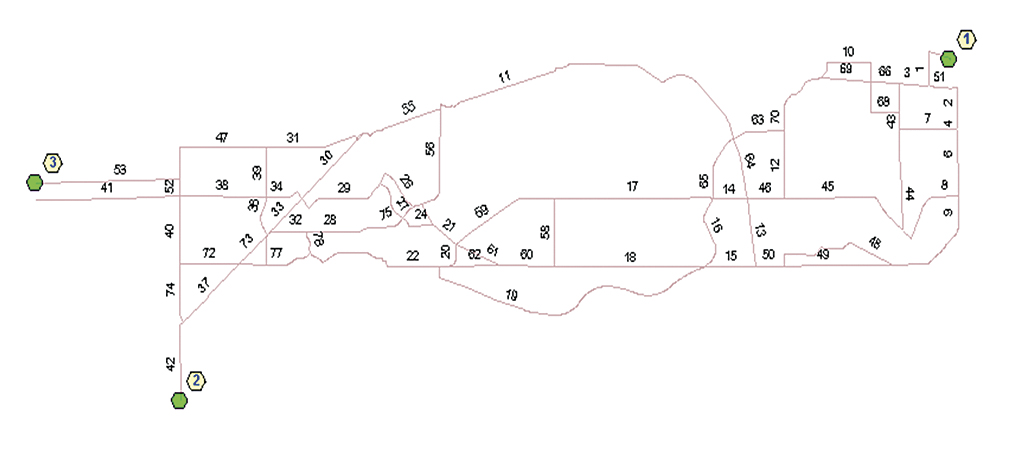
Optimizing a corridor from a nest of segments is similar to finding the directions through a network of roads—at least one attribute is required for the optimization process. Minimizing an objective function is the key to determining the best route. In this analysis, two attributes are used: total segment weight and cost. Once the decision matrix is populated with criteria weights and segment costs and scores for all criteria, it is important to import the segment weight and cost into the Pipe Segments feature class in ArcGIS. From ArcGIS, the application lets users browse for the Microsoft Excel decision matrix. Once the file is opened, the application looks up the segment weights and costs for each segment based on segment ID in the segments feature class and reads the data from Microsoft Excel cells, which contain weight and cost. The application highlights each cell in the decision matrix to indicate is has been successfully read. The application then appends three fields to the Pipe Segments attribute table. The SgLength field contains the length of each segment in map units, which is feet. The SgWeight field contains segment weights imported from the decision matrix. The SgCost field contains segment costs imported from the decision matrix. However, if these fields exist before the application runs, the values in these fields are just updated. Once the individual segments', weights and costs are imported from the decision matrix, the application is ready to perform the Network Analyst process. The application loops through the segment feature class and identifies all potential routes from the start node to the end node(s). The algorithm for this command minimizes the total weight of the segments comprising the current corridor. It does not take the cost of each segment into consideration in selecting the corridor but does keep track of the cost and sums it for each potential corridor.
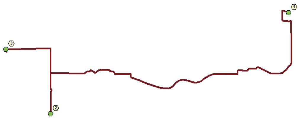
Table 1: Fields exported to the Best Corridors worksheet After successfully identifying routes, the application generates a new feature class and adds it to the active data frame in ArcGIS. The new date- and time-stamped feature class is saved in the application's Model Output folder. Each feature in this file is a potential pipeline route between origin and destination points. The number of potential routes is determined by the preset number of iterations. In summary, successful corridor identification requires
Each route can be viewed in ArcGIS geographically and exported to CAD, if desired. Also, the application reads the values from the attribute table of the output feature class and exports it to Microsoft Excel. In Microsoft Excel, the file contains only one worksheet named Best Corridors and a chart. Both can be saved if desired. (See Table 1) The application also generates a summary report for each run, if it's present in a dialog, and a Microsoft Word document that lists
While one "best route" may be sufficient in some cases, for most pipeline applications, a list of the top 20 routes will help decision makers arrive at a more well-informed choice. Because building transmission pipelines requires a large time investment and can have significant environmental and socioeconomic effects, determining pipeline routes deserves detailed analysis. This application can save time by automatically providing a list of potential routes. For major pipelines, the involvement of the public and other stakeholders in the decision-making process is paramount. The decision matrix and the dynamic process described are very useful. Stakeholders, agencies, and the public can be involved in assigning weights and scores to segments. Once that is done, the application can be run and, within a short time, a chart can be generated that ranks the top potential routes. Once a good algorithm is defined, automated route generation saves a lot of modeling time. By programmatically linking ArcGIS to Microsoft Excel/Word and/or CAD for further analysis and reporting, the application provides a user-friendly interface embedded into ArcGIS that lets users go through the optimization process. The linkage tool took about two weeks to program, test, and implement. The authors anticipate this tool will be used in future pipeline alignment projects. For more information, contact Ahmad M. Salah, GIS Specialist |