
Faced with the need to use large-scale electric facility data for smaller scale schematic circuit mapping, the City of Riverside Public Utilities Department employed many unique techniques to create these critical output products. Elegant approaches to scaling, placement, and page management usher several ARCPLOT commands including OVERPOST to the "next level." Peek under the hood to learn how OVERPOST really works and how to make it respect asymmetrical marker symbols. This article discusses the implementation issues, reveals AML fragments, and presents algorithms.
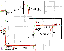
Detailed boxes clarify congested areas.
OVERPOST gone crazy. The annotation is scaled but is not concatenated into single strings.
The magneta markers represent the hidden markers that are used to trick the overpost bit map.
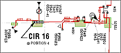
The completed circuit data. Annotation stacked neatly and close to the markers.
The Goal
The initial objective
of the City of Riverside GIS implementation was to replace all manually
maintained maps with a common base and department-specific data layers
to support the historical as well as enhanced map products. One of these
map products is the electric circuit map. AutoCAD and manual methods maintained
these maps. They were at various page sizes, orientations, and map scales.
The map scales ranged from 1" = 200' to 1" = 800' and the page sizes ranged
from A to D. The primary reason for the different scales, page sizes,
and orientation was to minimize total page counts while maintaining clarity.
Several inset maps clarified congested areas.
The electric department automated their facilities with a sophisticated database design using ArcInfo coverages and Oracle to support 1" = 100' inventory mapping. This scale, while very clear and easy to read, did not lend itself well to circuit mapping due to the number of pages required to cover each circuit. The engineering staff attempted various scales and page sizes before standardizing on one page size (D) and map scale (1" = 200'). Even at the standard scale, inset maps are required to detail congested areas.
Data Issues
We could manage most
of the data relationships within the electric data model by employing
creative RDBMS views and native mode SQL selects. For the uninitiated,
a native mode SQL select uses a relate that connects ArcInfo to the DBMS
using the format "^relate name" with a standard "where" clause to create
the selected set. The advantage of native mode selects is you can have
a very creative "where" clause collecting a selected set in the DBMS and
returning it to ArcInfo. In addition, the native mode queries perform
the query once and return the selected set of related records instead
of performing the query for each row. Here are good examples that explain
each:
The expression "reselect electric point transformer//KVA = 100" performs the query for each point and checks it against each row in the Oracle table.
The expression "reselect electric point ^transformer KVA = 100" goes to Oracle and returns the selected set of records that in turn select the set of electric points. This is unbelievably fast.
The only downside of native mode queries is that the ArcInfo data must be indexed on the relate item. This sounds obvious but when the data are edited, the index on the relate item is lost until the data are resaved. In most cases creative selects and processing can reduce the number of times edits blow away the index.
To optimize the circuit display requirements, we extracted the electric data from ArcInfo LIBRARIAN and processed it so that only the features represented in the circuit remained. When the data designed for 1" = 100' are simply mapped at 1" = 200', the annotation becomes too small and marker symbols overstrike, making the map unreadable. Several new data editing and processing steps as well as application issues resolved these problems.
Resolving
Application Issues
The next series of
issues unravel the annotation readability and marker placement. The problems
were initially addressed in four ways.
1. Rotate markers
to minimize overstrike.
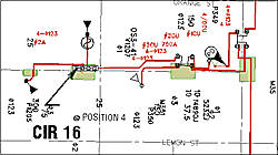
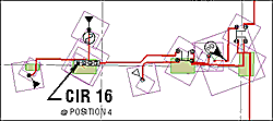
2. Use detail boxes to enlarge congested areas.
3. Scale up the annotation text sizes.
4. Use OVERPOST to move annotation dynamically.
Judicious editing eliminated marker overstrikes by properly rotating the markers. The 1" = 200' test plots were created to verify rotation effectiveness. Where necessary, detail or inset maps make sure that even in the most congested areas markers will not overstrike.
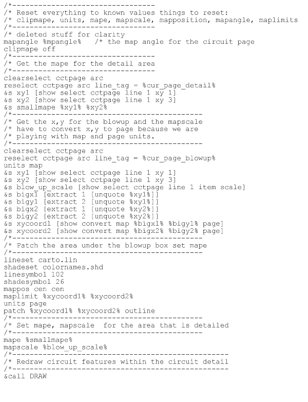
To create detail boxes for the circuit maps, we added two features to the circuit page layout coverage. The layout coverage is used to (page 20) denote how the circuit is mapped from the inventory data into the circuit pages where "pages" are created covering the entire circuit. Special annotation shows where other circuits connect to the other side of switches or help identify the circuit in the field.
For the detail boxes, we draw a box for the area to detail, pick the detail box map scale, and then place the detail box on the map where it will not affect the display of the rest of the circuit data. To make things even clearer, a leader line ties the detail box to the map location. The size of the detail box is calculated to precisely scale the data as selected in the detail area. The information drawn in the detail box is exactly the same as shown in the base but at a scale that is easily read.
Figure 1 shows the general series of steps used to get the map extent of the detail area, the map limits, and the scale at which to plot it.
Increasing the size of the annotation, which looked great at the original size, caused the text to overstrike. For the transformer and conductor annotation, individual text strings denote separate attribute values. Further data editing concatenated the individual strings reducing text overstrike.
Even with this editing, stacked text still overstruck in some instances, necessitating the use of the OVERPOST command to move annotation slightly to increase readability. The initial attempts at using OVERPOST were quite funny.
The first real attempt used the TEXT FIXED NODELETE option to keep the conductor annotation in place and the TEXT MOVABLE NODELETE to allow the device and structure annotation to float. Markers were plotted first with the MARKER FIXED NODELETE option set, blocking the bit map for the other text to float around them. Although they were not usable, these early attempts showed promise.
Using the OVERPOST command required some innovative thinking. Separate stacked text strings that "went together" were moved individually and were separated. We had to exercise some annotation data relationships to process the data and assemble the individual parts into one text string so they would move as a unit.
The process was to use the annotation linkage to the device, the device knowledge of its structure, and the structure linkage to its annotation to tie everything together. We were getting somewhere, but annotation could still be confusing in some places.
At this point we really understood the fact the OVERPOST command moves points or text based on its origin. For many annotations, the original placement designed to support the display of all the electric data caused some of the text placement to be too far away for clear identification. By using our data relationships, we moved the annotation on top of the associated electric devices or structures. The OVERPOST command would then move the string away from the new origin point, preventing overstrike with other points and text. By using the LEADERSYMBOL, LEADERTOLERANCE, and LEADERS commands, we were able to clarify what went where even when it was far away.
We were still not happy with the results of our efforts because in most cases we had leader arrows trailing all over the place. Since we could not control the order in which the annotation was placed, we had some cases where leaders crossed over each other.
After talking with Esri and through trial and error, we determined our specialized marker symbols resulted in OVERPOST bit maps that were blocking an area much larger than the actual marker. We called this the bounding box versus the ink-on-the-page problem. Because many of our markers are very large and are not centered around the midpoint of the marker block, we were caught by this trap in a big way. Fortunately, we crafted a solution by plotting white boxes that closely bound each of our symbols, turned OVERPOST off, plotted the real markers, and then turned OVERPOST back on to plot the annotation.
The final issue to fix was the instances where annotation was placed over line work. The OVERPOST environment did not take into account line work in the bit map. Overcoming this was easy. We used the DENSIFYARC command with the VERTEX option to create new vertices every foot. Then we used ARCPOINT, the resulting coverage to create points for all of the nodes and vertices. We simply plotted all of the points with a small white marker to set the bit map for all of the lines.
Summary
By using a creative approach to processing the data in a specific way,
by understanding the limitations of OVERPOST, and by tenaciously pursuing
our course, we were able to reuse GIS data developed by the City of Riverside
for inventory mapping at one scale and use it at another scale for circuit
mapping. Many people at the City who saw our early attempts doubted we
could ever pull it off. It was nice to prove it could be done.
About the
Authors
Brad Mayo is the public
utilities CADME database administrator and lead programmer for utility
applications for the City of Riverside, California. Mayo earned a bachelor's
degree in geography and has done additional college work in computer programming
at California State University at San Bernardino.
Pat Hohl is a senior electric engineer with the City of Riverside, California Public Utilities Department. He received a bachelor of science in electrical engineering from Drexel University.
Mayo and Hohl teach
GIS classes at University of California Extension and have coauthored
the ArcView GIS Exercise Book. Hohl edited GIS Data Conversion: Strategies,
Techniques, and Management. Both books are available from the GIS Store
or by calling 1-800-447-9778. ![]()