Understanding the structure, extent, depth, and distribution of subsurface materials is important for many disciplines, including geology, mining, oil and gas, and hydrogeology. With the advances in 3D capabilities, GIS-based packages have been developed to integrate GIS into the world of 3D subsurface modeling and visualization.
The creation of a subsurface model of the northern part of the Gulf Coast Aquifer in Texas was the primary objective of a project completed by Esri Partner Intera Inc. (Austin, Texas) in association with Esri Partner Aquaveo LLC (Provo, Utah). The purpose of the project was to provide stratigraphic surfaces and sand thickness maps of the geologic formations that compose the Gulf Coast Aquifer. The project is part of a long-term plan (sponsored by the Texas Water Development Board) to update groundwater availability models that are used for water resources planning and management for Texas. To develop a groundwater model simulating the flow of water within the subsurface, one has to first understand the hydrogeology of the system and estimate the physical properties of underlying aquifer layers and confining units. Thus, a detailed and accurate description of the subsurface is essential for developing accurate models.
By its nature, creation of a 3D realistic subsurface model is complex and requires integration of many datasets (usually from different sources), such as digital elevation models, borehole records, geologic maps, and hydrography. Common data products in the process of creating a 3D subsurface model include borehole logs, 2D cross sections, 3D fence diagrams, surfaces representing terrain or top/bottom elevations of units, and 3D volume elements. The use of GIS datasets in their native format and integration of all the information into a single geodatabase streamlined the process of building the 3D subsurface model and later updating and maintaining the model as new information is obtained.
The Subsurface Analyst toolset, available as part of the Arc Hydro Groundwater tools, was used to integrate the necessary information, create cross sections in ArcGIS for Desktop, transform the cross sections into 3D features, and build a 3D subsurface model.
For this study, the Gulf Coast Aquifer has been subdivided on the basis of chronostratigraphic correlation to yield subaquifer layers. The aquifer system is composed of four units—from shallowest to deepest, the Chicot Aquifer, the Evangeline Aquifer, the Burkeville Confining System, and the Jasper Aquifer. Each of the units was further subdivided into subunits, resulting in a set of 10 hydrogeologic units. The basic workflow started with identification of aquifer layer boundaries along boreholes, based on drilling and geophysical logs, and then systematic correlation of layers throughout the study area.
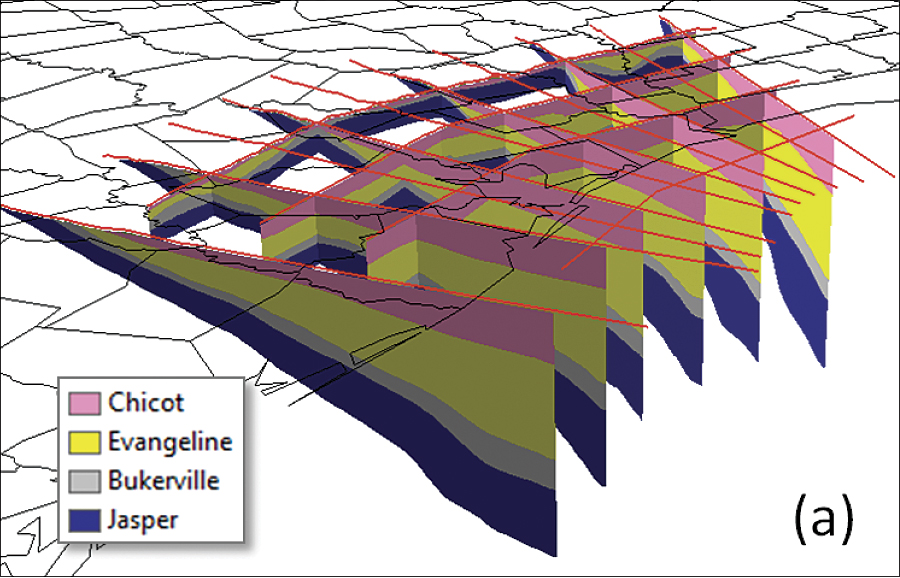
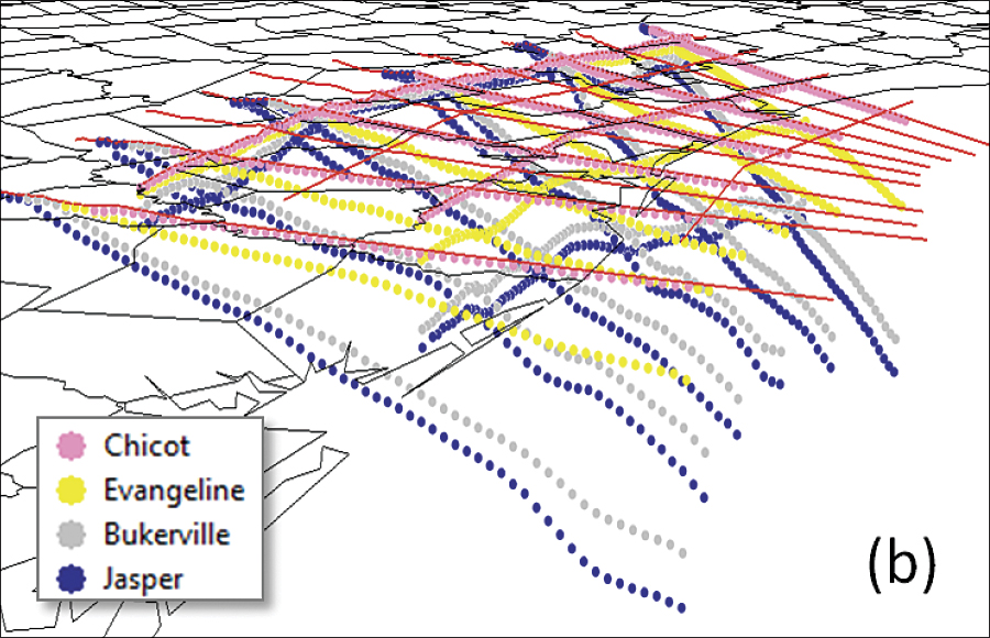
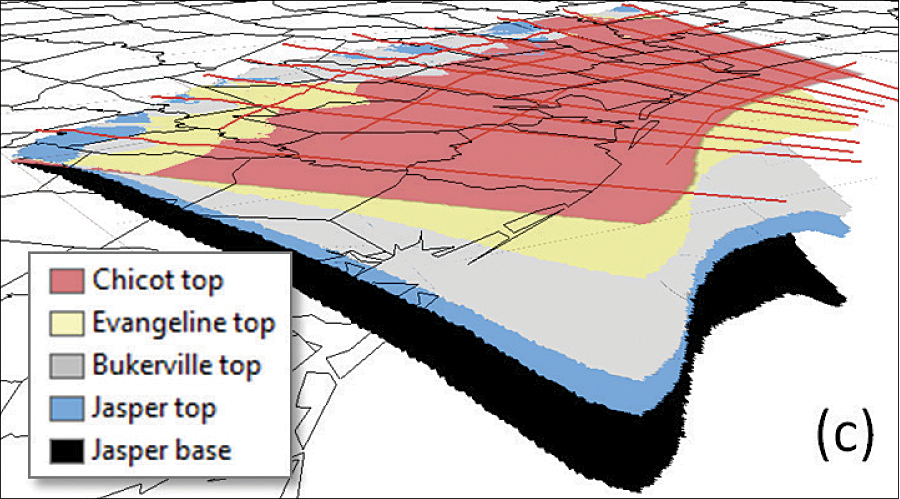
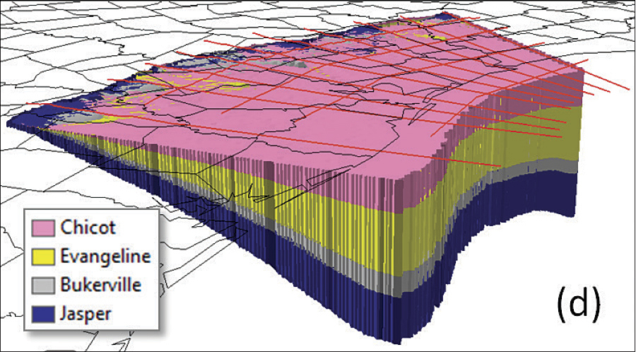
To support the correlation, a grid of cross sections was created covering the model domain. For each cross section, a set of panels was sketched based on borehole logs, the digital elevation model, and geologic maps, together with the best geologic knowledge of the area. The creation of the cross sections and the sketching process was all done within ArcGIS using the Subsurface Analyst cross section tools. Each cross section is created in a separate data frame setup using the Cross Section wizard, and different types of information are projected onto the cross section.
The sketched 2D cross sections are the base for developing a 3D subsurface model. Although not part of the original project, a workflow was developed to support the creation of a 3D subsurface model from the sketched cross sections. The workflow includes the following steps:
- The sketched 2D cross section panels were converted into GeoSections (3D multipatch features) that enable viewing hydrogeologic layers as a 3D fence diagram.
- The 3D GeoSections were sampled to create a set of new 3D points, where each point represents the top or base of a hydrogeologic unit.
- Raster surfaces were interpolated from the points using ArcGIS Spatial Analyst interpolation tools. Each raster represents the top or bottom of a hydrogeologic unit.
- GeoVolume (3D multipatch features) features were created by “filling” between the raster surfaces to display hydrogeologic units as 3D volume elements.
This project is an excellent example of how GIS-based workflows can support the development of subsurface models. The ability to integrate a wide array of spatial datasets into a single geodatabase, automate parts of the data processing, and visualize the results in real spatial context proved invaluable for the project.
About the Authors
Daniel M. Lupton is a hydrogeologist with Intera Inc., Austin, Texas, and Gil Strassberg is a senior product engineer for Aquaveo LLC, Provo, Utah.
For more information, contact Daniel M. Lupton, Intera Inc., or Gil Strassberg, Aquaveo LLC (web: www.aquaveo.com/archydro).
