Sometimes it is useful to indicate the direction of a line on a map. The most common way to do this is to add an arrowhead at the end of the line. This also often makes reading the map more intuitive.
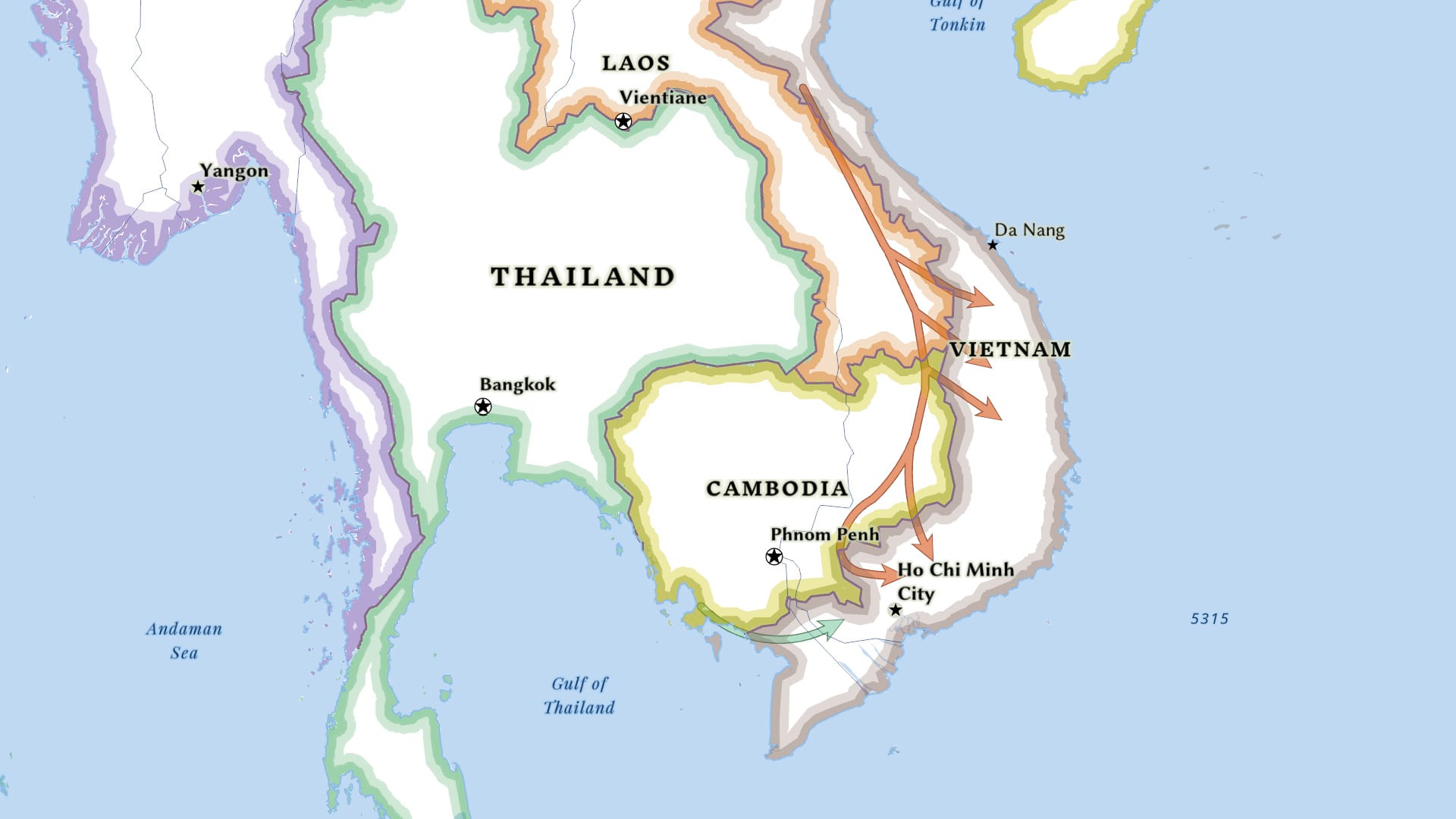
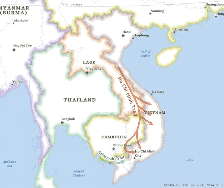
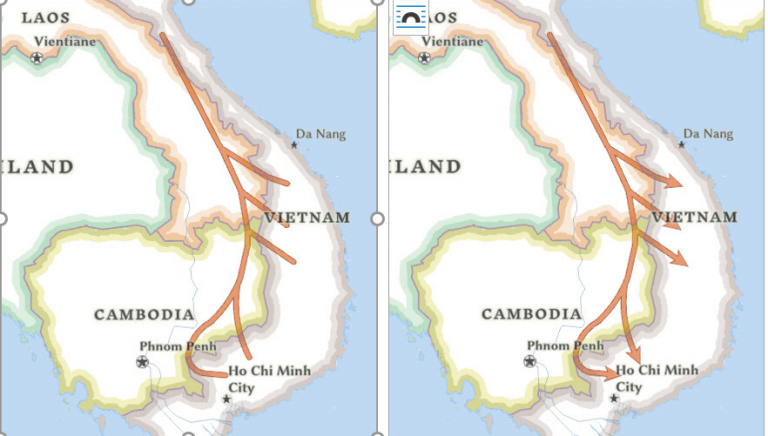
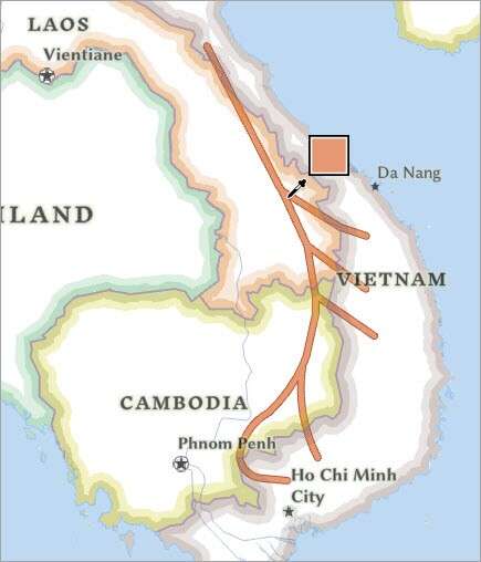
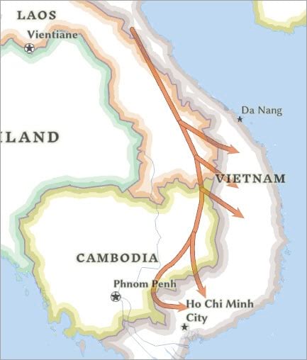
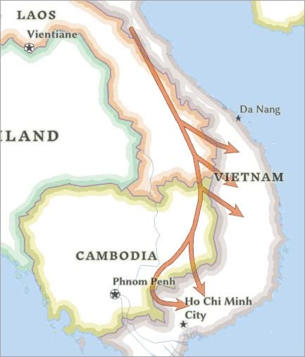
For example, on this map showing current political boundaries (below), arrowheads indicate the direction of the flow of military caches and other supplies from North Vietnam and Cambodia to the Vietcong in South Vietnam during the Vietnam War period (1955-1975). (The original source for information on the location of these supply lines is The Making of America: The History of the United States from 1492 to the Present by Robert D. Johnson and published by National Geographic.)
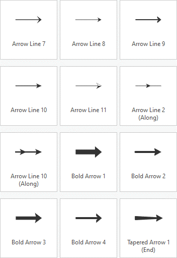
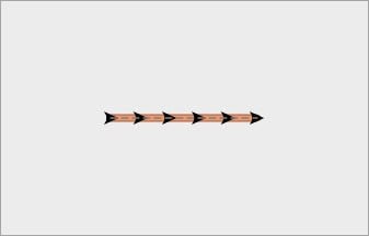
There are more options for adding arrowheads to line symbols now because a new set of arrowheads was released with ArcGIS Pro 2.7, giving you a wider selection to choose from. Also, in ArcGIS Pro 2.7, 57 new line symbols were added to the symbol gallery, including lines with arrowheads. You will find a sample of this collection below. If you want to use a simple line symbol, you can choose one from the gallery.
This tip assumes you are familiar with ArcGIS Pro and have intermediate level skills. In this tip you will learn how to make a complex line symbol that includes a casing, or outline, around the line and the arrowhead. This technique for modifying symbology in ArcGIS Pro may be useful for other point and line symbols.
To learn how to refine arrowhead line symbology, download this project package and follow these steps:
- Add the arrowhead to the line
- Change the arrowhead’s appearance
- Use symbol level drawing to refine the arrowhead’s appearance, if necessary
- Import the symbology to change the appearance of additional lines, if desired
Add the Arrowhead to the Line
- Download the map package and open it in ArcGIS Pro. Note that the map in this project contains two line layers you will modify (Ho_Chi_Minh_Trail and Sihanouk_Trail) and two line layers that show the finished symbology (Ho_Chi_Minh_Trail (final symbol) and Sihanouk_Trail (Ho_Chi_Minh_Trail and Sihanouk_Trail).
- On the Contents pane, click the Ho_Chi_Minh_Trail line layer to select it. On the ribbon, the Feature Layer contextual tab set appears.
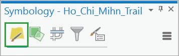
- On the Feature Layer contextual tab, click the Appearance In the Drawing group, click Symbology ().
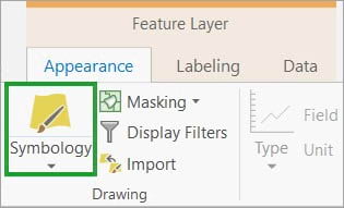
The Symbology pane appears, and the Primary symbology tab () is selected.
The primary symbology method is Single Symbol, which means that all features in the layer are drawn with the same symbol. (In this case, the layer only has one feature.)
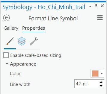
5. Next to Symbol, click the symbol.
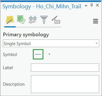
The pane then shows symbol formatting options for the selected line symbol.
- At the top of the Format Line Symbol pane, click the Gallery tab and then click the Highway symbol to select it.
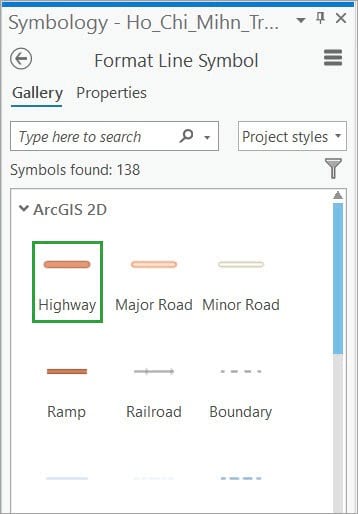
Your symbols may be arranged in a different order.
The symbology for the line layer then updates on the map and on the Contents pane. This is a good start, but you want the symbol to have an arrowhead at the end.
7. At the top of the Symbology pane, click the Properties tab.
The Properties tab has three graphical tabs under it. On the Symbol tab (), you can change symbol properties such as fill color, outline color, and outline width. On the Layers tab (), you can change properties of the graphical elements (symbol layers) that the symbol is composed of. This gives you more control over the symbol’s appearance. And on the Structure tab (), you can change the symbol’s structure by adding and removing symbol layers. You can also apply effects.
8. Click the Structure tab ().
9. Under Layers, click Add symbol layer. On the drop-down menu, click Marker layer.
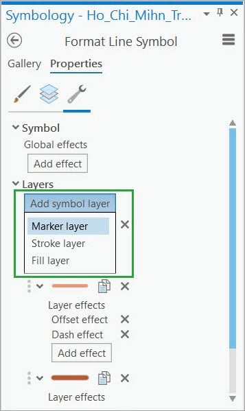
The marker layer is added above the two existing stroke layers—the thin, light orange line and the thick, dark orange line. The result is previewed in the window at the bottom of the pane.
Now that you have added the marker layer, you will change it to an arrowhead on the Layers tab.
10. Click the Layers tab ().
11. Click the Shape marker symbol layer to work with its properties. Under Appearance, click the Font form button.
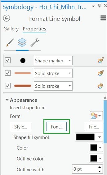
The Choose a character window opens.
12. Change the font to ESRI Arrowhead and select an arrowhead.
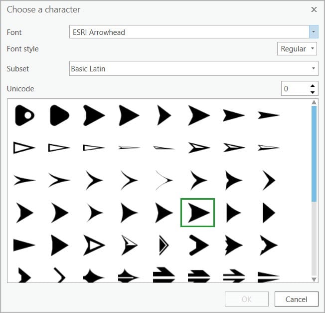
- Click OK.
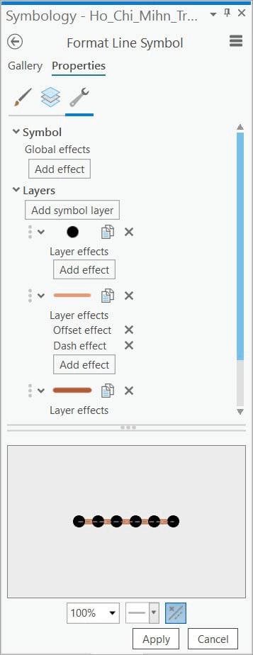
The new symbology is shown in the preview.
The next step is to change the appearance of the arrowhead so that it is larger, matches the color of the line, and is positioned at the end of the line only.
Change the Arrowhead’s Appearance
- On the Symbology pane, click the Properties tab and click the Layers tab ().
- Under Appearance, click the Color drop-down arrow. At the bottom of the color palette, click the Eyedropper tool () to activate it.
Note: The Eyedropper tool is available wherever a color palette is present. You can use the tool to pick a color from a layer in the active view and apply it to the current symbol. When the Eyedropper tool is active, a square magnifier appears with the pointer to show the currently selectable color. To apply the color to the symbol, left-click the map, scene, or layout. After a color has been clicked, the symbol’s color is set to the new color and the tool deactivates.
To learn more, see the online help page on color and the Eyedropper tool.
- On the map, click the Eyedropper tool on a location that shows the interior color of the line.
At the bottom of the Symbology pane, the symbol preview shows that the interior line color has been applied to the arrowhead.
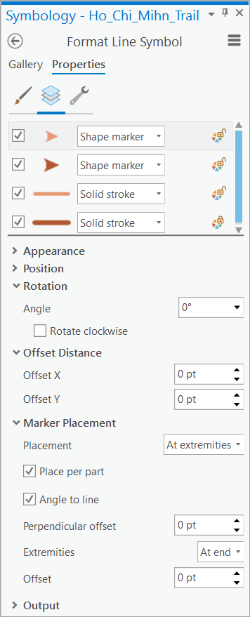
4. Click the arrow to the left of Marker Placement to expand this section and show the options.
5. Click the Placement drop-down arrow and click At extremities.
6. Click the Extremities drop-down arrow and click At end.
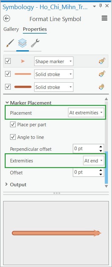
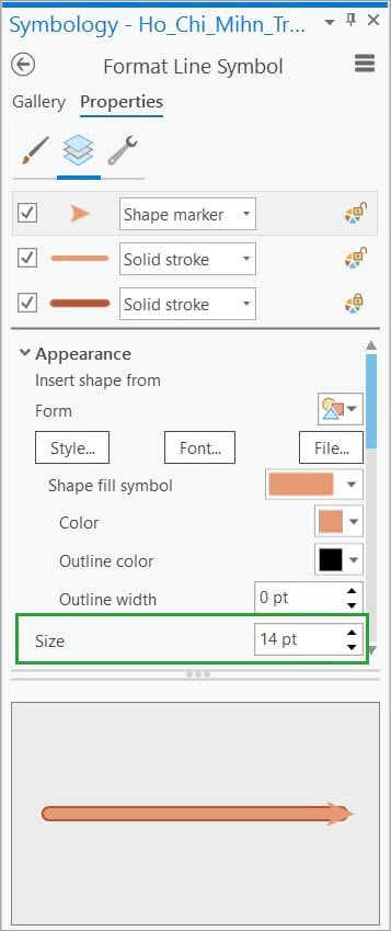
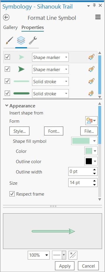
- Under Appearance, change the Size to 14 pt to fit the width of the line.
8. Click Apply.
The new symbology is applied to the map.
Note: If the arrowhead is displayed at the beginning of the line instead of the end, reverse the direction of the line as described in this online help topic: Reverse the direction of a polyline.
To save time, you can create the casing (outline) for the arrowhead by duplicating the marker layer and modifying its properties. The next two steps show how to do this.
9. Click the Structure tab ().
10. On the Structure tab, next to the arrowhead, click Duplicate layer.
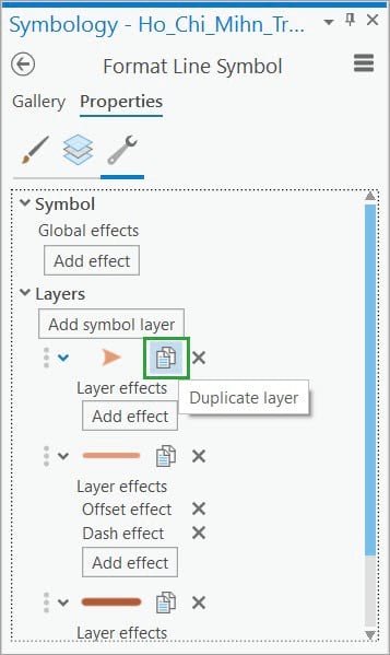
The new marker layer is added above the three existing layers in the symbol.
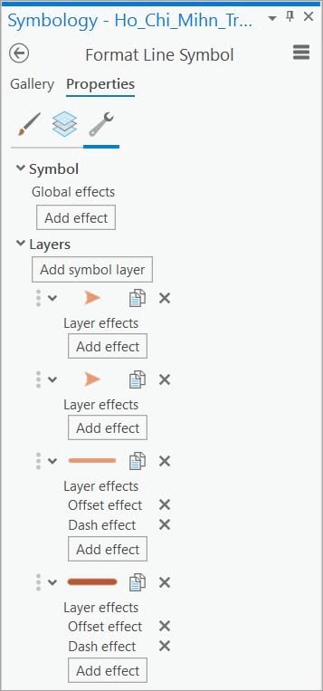
Now that you have added the second marker layer, you will modify its size and color.
11. Click the Layers tab ().
12. Click the second Shape marker symbol layer (above the first stroke layer) to work with its properties.
13. Under Appearance, click the Color drop-down arrow. On the color palette, click the Eyedropper tool.
14. On the map, click the Eyedropper tool on a location that shows the exterior color of the line.
15. Change the Size to 17 pt.
16. Click Apply.

Use Symbol Level Drawing
You can use symbol level drawing to make the lines and arrowheads appear seamlessly connected. This will eliminate the casing in the interior of the symbol that is shown above.
When symbols have more than one symbol layer, symbol level drawing (shown as symbol layer drawing in the Symbology pane) can be used to control how the individual symbol layers are ordered. To learn more, see this online help topic: Symbol level drawing.
- Select the line layer on the Contents
- In the Drawing group in the main menu, click On the Appearance tab in the Feature Layer contextual tab, on the Appearance tab, in the Drawing group, then click the Symbology button ().
- On the Symbology pane, click the back arrow to access the Symbol layer drawing tab (), then turn on Enable symbol layer drawing.
Note: If you later decide to disable this, all the settings will be maintained in case you want to enable it again.
- Click the Advanced
- Click the arrow next to each group to expand it.
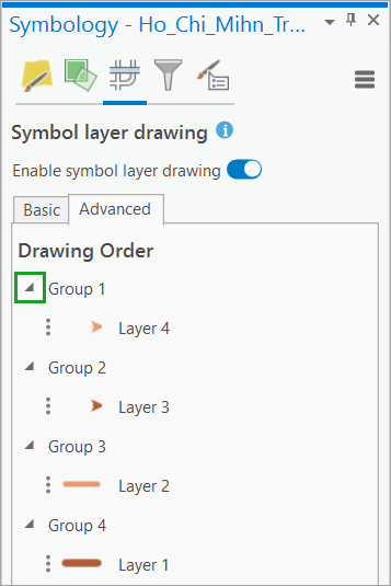
6. Drag Group 3 above Group 2.
The lines and arrowheads now appear connected and the casing is shown around all the edges.
Import the Symbology
Now that you have created the desired symbology for one layer, it can be imported and modified to symbolize another layer.
- Select the Sihanouk Trail feature layer on the Contents
- On the Symbology pane, click Import symbology ().
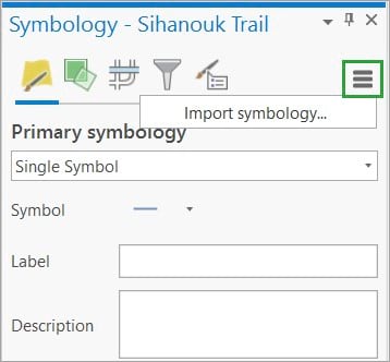
Note: Optionally, on the Feature Layer contextual tab, on the Appearance tab, in the Drawing group, and click Import ().
The Apply Symbology From Layer geoprocessing tool opens, and the Input Layer parameter is set to the current feature layer.
3. Set the Symbology Layer parameter to the layer that contains the symbology you want to import.
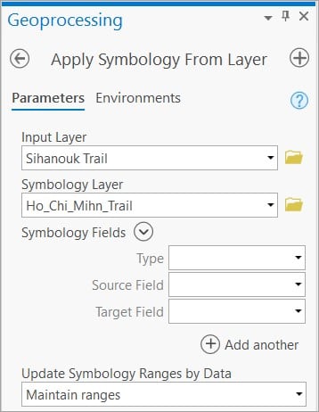
4. Click Run to execute the tool and apply the imported symbology to the current layer.
5. On the Symbology pane, next to Symbol, click the symbol.
6. Click the Layers tab ()
7. Under Appearance, for each symbol layer, change the color to match Sihanouk_Trail (final symbol) or any other desired color for the final symbol to create the desired symbol.
8. Click Apply.
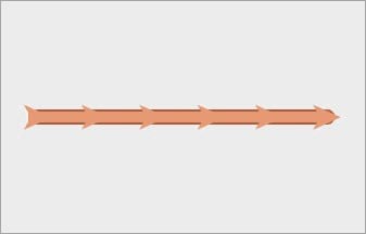
The desired symbol is now displayed on the map.

You can use this workflow to modify other properties of the markers and lines. The many marker options allow points symbols to be placed along the lines, at both ends of the lines, offset from the lines, and more.
This tutorial shows how line feature layers can be modified with the addition of shape makers, casing, and use of symbology layers to create directional arrows that more effectively communicate the information in the map. Once created, modified symbology can be imported and reused. Look carefully and you will see just how often this technique is used on professional looking maps.
To learn more, see this online help topic: Position and place marker symbol layers.
