Reality mapping allows ArcGIS users to interact with a digital world that shows places and situations as they truly are, enriched with layers of geospatial data to add greater context. ArcGIS Reality for ArcGIS Pro is a new extension to ArcGIS Pro which enables users to expand their GIS workflows by generating survey-grade geospatial products, such as true orthos, point clouds, 3D meshes, and digital surface models, using drone, aerial, and satellite imagery. The product is already quickly gaining traction with GIS professionals in the AEC, utilities and National, State and local Government sectors where using digital representations of the real world offers better, faster decision making.
ArcGIS Reality for ArcGIS Pro is part of Esri’s ArcGIS Reality suite of photogrammetry software products for 3D reality mapping. It allows users to perform reality mapping at scales ranging from sites to countries. One of the major benefits of ArcGIS Reality for ArcGIS Pro is its native integration into ArcGIS Pro – our leading desktop software for geospatial analysis. This means that you can now use the ArcGIS Reality for ArcGIS Pro extension inside of ArcGIS Pro to process imagery from drones into 2D orthomosaics and 3D meshes and then continue your analysis in ArcGIS Pro without having to switch between different applications. The inclusion of ArcGIS Reality into ArcGIS Pro also means that the whole process of generating 2D and 3D outputs can be streamlined using GP tools.
During our talks with our clients about ArcGIS Reality, we learned that quite a few people wanted to automate this workflow but were not sure how to get started. One of those clients, Massachusetts Department of Transportation (MassDOT), had an interesting use case. MassDOT has a program in which they fly drones over all of their assets and create 2D orthomosaics from the imagery they collected. They were working with another cloud software and had to constantly download their products and then use ArcGIS Pro to publish images services so that other stakeholders could use the information. When they heard about ArcGIS Reality, they were eager to try it out and were very pleased with the ease of use and the integration into ArcGIS Pro, which they were already using. During one of our meetings, they asked if they could automate the process which triggered the need to document this process so that other clients could implement this workflow as well.
In this blog we will provide step by step instructions that will walk you through the process of creating a ModelBuilder model in ArcGIS Pro, add the necessary GP tools needed to process drone imagery. Once you have the products created by ArcGIS Reality, you can publish them as services in ArcGIS Online or ArcGIS Image Server.
The general workflow to process drone imagery includes the computation of a camera model, extraction of tie points in each image, Bundle Block Adjustment of the image location and orientation and then reconstruction of the 3D point cloud into additional output products such as a True Ortho, Digital Surface Model and a 3D mesh. ArcGIS Pro has hundreds of GP tools which can be accessed from the Tools pane and can be linked together through ArcGIS Pro ModelBuilder. The GP tools required for drone image processing are listed here:
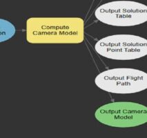
- Compute Camera Model – estimate the camera model from the initial image data and refine it
- Compute Tie Points – find tie points between overlapping images
- Compute Block Adjustment – calculate the accurate location and orientation of the images using tie points and the initial camera information
- Apply Block Adjustment – set the location and orientation of the images to the results calculated in the Compute Block Adjustment tool
- Reconstruct Surface – generate outputs such as True Orthos, point clouds and 3D meshes
Our first step in the workflow is to create a Reality Workspace in ArcGIS Pro. This will create a mosaic dataset that will house the image information for your project and serve as the basis for the GP tools to work on. For a drone project, follow the steps detailed in our documentation website and then continue to the next step.
Now that we have a project and a Reality Workspace in ArcGIS Pro, we can create a new ModelBuilder environment. In the Analysis tab of ArcGIS Pro, press the ModelBuilder button to create a new model.
In this new model, we will bring in the different GP tools listed above, connect them, and configure some of their parameters. We can find each GP tool by going to the Analysis tab of ArcGIS Pro and pressing the Tools button and then search for each tool in the “Find Tools” search bar.
We will start with finding the “Compute Camera Model” tool and then dragging it into the Model we created. The tool needs a Mosaic Dataset as input so we will drag into the model the “Image Collection” mosaic dataset which was created as part of the Reality Workspace. This can be found in the Reality Mapping pane under the “Source Data” layer group.
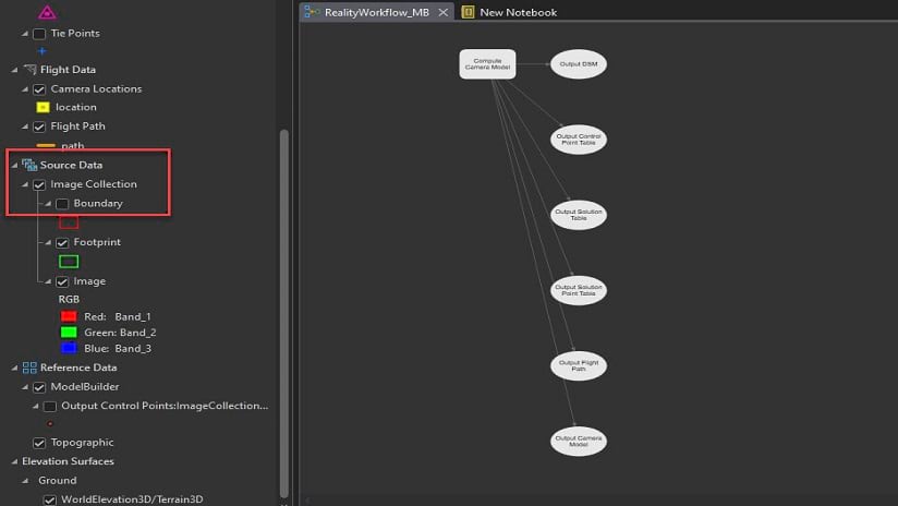
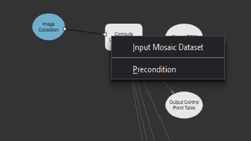
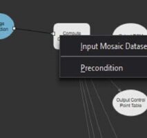
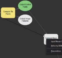
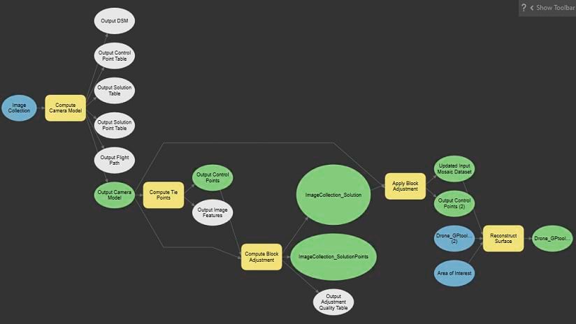
Now, we will connect this mosaic dataset to the “Compute Camera Model” tool by dragging a line from the “Image Collection” box to the “Compute Camera Model” box. When we connect to the GP toolbox it will show a pop-up with the option to define this as the Input Mosaic Dataset. Now we have the first process complete it will show the “Output Camera Model” in green to indicate that the process has been configured correctly. In some of the screenshots we have changed the layout slightly by pressing the “Auto Layout” button in the ModelBuilder tab. This helps us organize the different components of our model in a way that’s easier to understand.
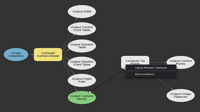
We continue by finding the “Compute Tie Points” tool and dragging it into the model. This tool also requires a Mosaic Dataset as input, so we will define the “Output Camera Model” as the input and drag a line from this box to the “Compute Tie Points” box and select the Input Mosaic Dataset option. With this process complete we will see the “Output Control Points” box colored in green.
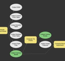
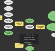
Our next step is to find the “Compute Block Adjustment” tool and drag it into the model. This tool requires a mosaic dataset and a control points table as input. We connect between the “Output Control Points” box and the “Compute Block Adjustment” box (defined as Input Control Points) and between the “Output Camera Model” box and the “Compute Block Adjustment” box (defined as Input Mosaic Dataset).
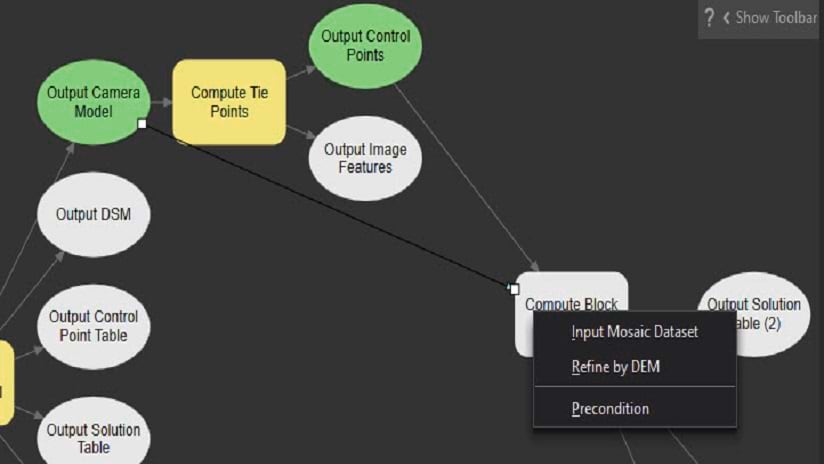
Once you have connected the boxes make sure to double-click the “Compute Block Adjustment” box and set the “Transformation Type” parameter to “Frame camera model”. This will ensure that the Bundle Block process uses the frame camera information in the image metadata.
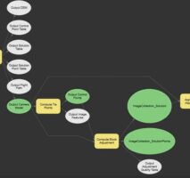
Now we can search for the “Apply Block Adjustment” tool and drag it into the model. This tool requires a mosaic dataset and a solution table as input so we will connect the “Output Camera Model” box and the “Apply Block Adjustment” box (defined as Input Mosaic Dataset) and between the “Output Solution Table” box (named here “ImageCollection_Solution”) and the “Apply Block Adjustment” box (defined as Input Solution Table).
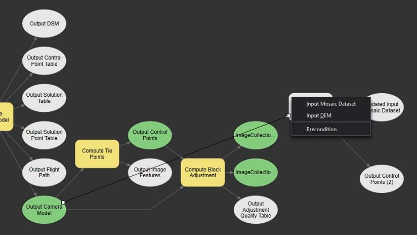
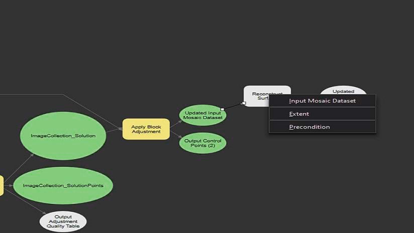
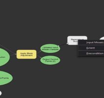
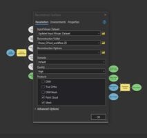
With these processes defined, we can now find the “Reconstruct Surface” tool and drag it into the model. This will require a Mosaic Dataset as input, and we will define it by connecting between the “Updated Input Mosaic Dataset” box and the “Reconstruct Surface” box and defining it as the Input Mosaic Dataset. Once we have established this connection, double-click the “Reconstruct Surface” box and in the “Products” list check the different products you wish to generate in this workflow. In addition, review the “Reconstruction Folder” and make sure you define the output folder where your results will be stored.
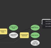
We now have a complete workflow that can process the input imagery into various output products. This workflow will use the default parameters defined for each tool, so it is recommended to first run it over a small area and determine if any of the parameters need to be modified to obtain more accurate results or reduce processing time.
Now, the output products generated by this workflow are stored locally on a folder defined in the “Reconstruct Surface” tool.
But what if you want to publish your results as image services and scene layers in ArcGIS Online of ArcGIS Image server?
For orthomosaics and surface models, ArcGIS Pro has a wizard workflow to help you create an image service by pressing the “Create Hosted Imagery” button in the “Imagery” tab. For the point clouds and 3D meshes you will need to first find the SLPK files in your workspace “Products” folder. For each SLPK file, right-click and select “Share Layer” to start the publishing workflow.
Alternatively, Courtney Lusk from the Imagery GBD team has created a short python script (which she has converted into a GP tool) that can search through the output folders, find the Tiff and SLPK files and upload them to your ArcGIS Online or ArcGIS Enterprise organization as a TPK or SLPK file. Once uploaded, the TPK or SLPK will be automatically published as a Tile Layer or Scene Layer. You can find the tool and documentation on this GitHub page.
The process we described here assumes data has been captured accurately but it is always recommended to add Ground Control Points to your workflow to ensure your outputs are as accurate as possible. Also, you can break up this workflow into different parts and configure them in Tasks so that any team member can run them. More information on how to create Tasks in ArcGIS Pro can be found here.
We hope you enjoyed this blog post and found it useful, and we look forward to hearing your feedback in the comments section.


Article Discussion: