
Imagine a typical urban planning project where planners, urban designers, and consultants are collaborating on the latest development proposal. While ArcGIS Urban serves as the shared platform for planning and scenario evaluation, much of the design information continues to be created and exchanged in Autodesk AutoCAD DWG format. Updated building footprints, parcel layouts, and site plans regularly move between teams, creating a constant need to transfer data between CAD and GIS environments.
For ArcGIS Urban users, integrating DWG data is not a straightforward task. The process often requires additional preparation and validation steps to ensure information is accurately represented in ArcGIS Urban.
With ArcGIS for AutoCAD, however, this workflow becomes significantly simpler. The integration is precise, efficient, and easy to manage, allowing planning and design teams to move data from AutoCAD into ArcGIS Urban with ease.
In this article, you will learn how to streamline the connection between CAD and GIS workflows by bringing your 2D drawings into 3D in ArcGIS Urban using ArcGIS for AutoCAD. You will also learn how to evaluate metrics such as the floor space distribution by usage type, analyze shadow cast, or compare against zoning regulation.
Try it with your own data:
This example demonstrates a complete CAD-to-GIS workflow that you can follow using your own AutoCAD drawings. If you’re new to ArcGIS for AutoCAD, download the app and follow along to see how easily parcel and building footprint data can be brought into ArcGIS Urban for planning and scenario evaluation.
Prepare data in AutoCAD
To use CAD data in ArcGIS Urban, it must be correctly positioned in the real world. This starts with assigning a coordinate system and ensuring the drawing is accurately located. ArcGIS for AutoCAD provides tools to define a coordinate system, adjust the drawing’s location when needed, and verify its placement using Esri basemaps.
1. Set up the AutoCAD file
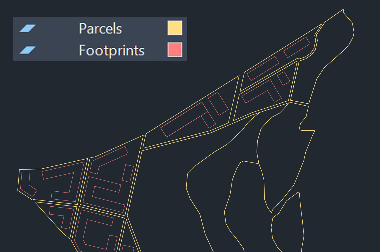
For simplicity, our AutoCAD example starts with only two layers: parcels and building footprints.
-
Step 1: Geolocation and Coordinate Reference System (CRS)
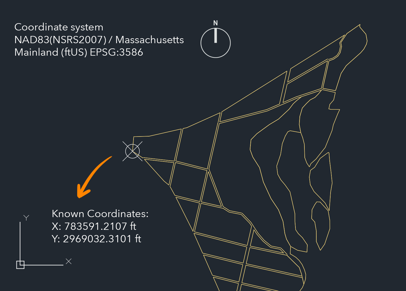
Before sharing CAD data with ArcGIS Urban, the drawing must be correctly positioned in the real world. To do this, you need to know the Coordinate Reference System (CRS) and the coordinates of at least one known point in the drawing.
For detailed info about setting a coordinate system using ArcGIS for AutoCAD, see Esri coordinate systems.
If the drawing has already been geolocated, you can skip ahead to Step 3.
In this example, we’ll assign a coordinate system and use a known reference point to place the drawing in its correct geographic location.
The example shows the usual scenario where 2D projected parcels are correctly oriented, with true north aligned to the positive Y-axis.
Verify that the units are correct and that the drawing is at the right scale.
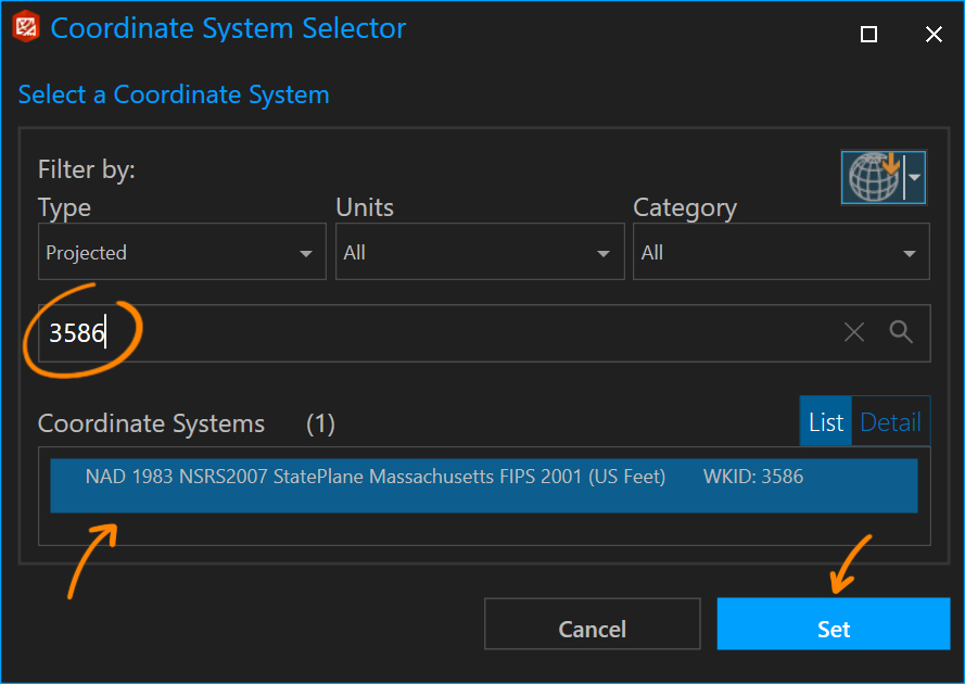
From the ArcGIS tab, navigate to Coordinate System > Assign to access the Coordinate System Selector, where you can search for and set the CRS of your data.
-
Step 2: Moving the data to a known coordinate point
Using the Move tool, we can reposition the drawing in 2D space to a point with known coordinates.
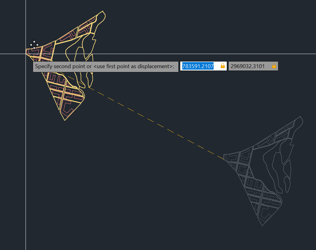
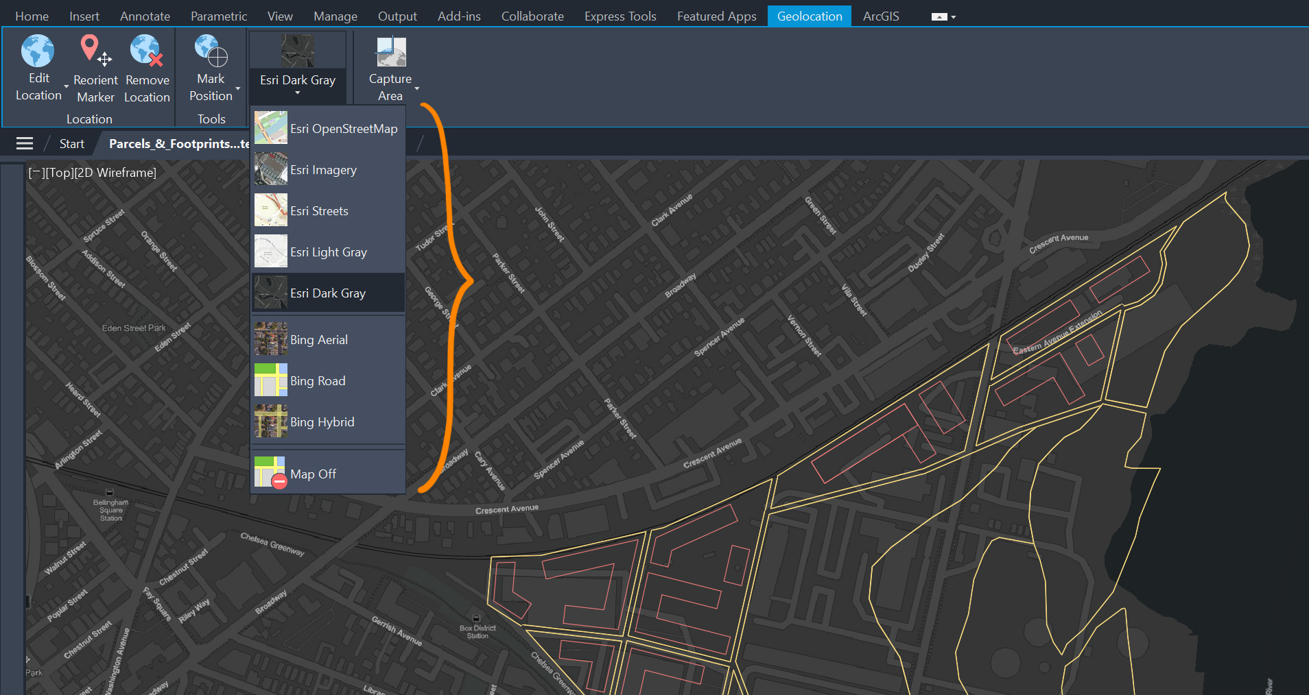
Now, from the Geolocation tab, turn on any available basemap to confirm that the drawing is positioned correctly on the map:
-
Step 3: Organize the building footprints
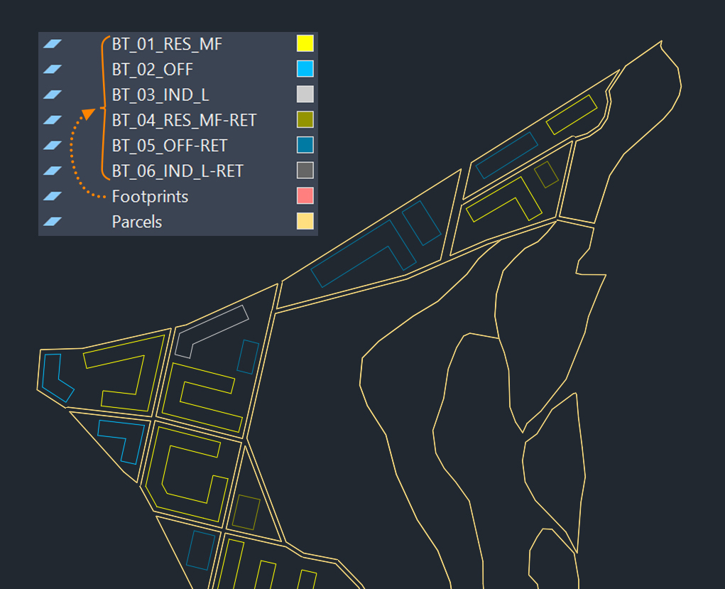
To determine which footprints will correspond to which building type in ArcGIS Urban, we need to organize the footprint polylines into separate groups. We can use AutoCAD properties such as layer, color, block, or line type as grouping criteria.
In this example, we will use layers to define the groupings by building types. Therefore, the footprint polylines will be assigned to the layer corresponding to their building type, for example RES_MF (=Residential Multi-Family) or OFF-RET (=Office with Retail).
Keep in mind:
AutoCAD polylines must be closed to be exported as polygons in the feature layer.
2. Create document feature layers from the CAD layers
Before the CAD data can be shared to ArcGIS and used in Urban, the CAD layers need to be converted into GIS feature layers.
There are two ways to do that: by creating a new feature layer or with automation.
-
General option: New Feature Layer
This example uses the generic “New Feature Layer” option, which provides greater control over the process.
In this workflow, we name each feature layer after its corresponding CAD layer.
As shown in the animation below, repeat this process for each building type sublayer.
Keep in mind:
When creating document feature layers, you should set the geometry type to Polygon. Otherwise, ArcGIS Urban will not be able to use them as parcels or building footprints
-
Automated options
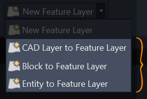
As an alternative to the general option, from the New Feature Layer drop-down menu, you can automatically create feature layers based on different criteria, such as CAD layer, block, or entity type.
3. Share feature layers
Next, share the document feature layers as web feature layers, so that they can be accessed and used across ArcGIS. Use the Share to ArcGIS button to sign in to the target portal and publish the feature layers.
-
Share as a hosted feature layer
We share a single hosted feature layer that contains the selected parcel and footprint sublayers.
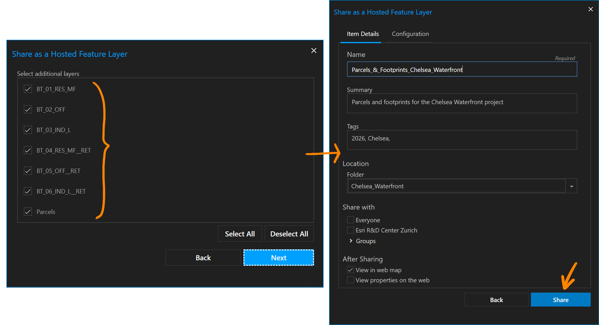
After sharing, the document feature layers appear as web feature layers in the Esri Contents pane.
By default, all AutoCAD polylines that are shared as web feature layers are automatically moved to new AutoCAD layers with the ‘ESRI’ prefix.
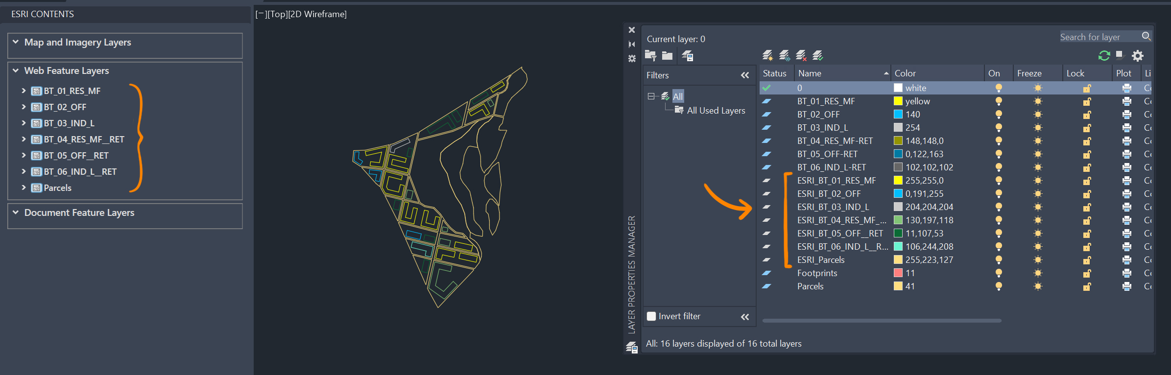
Note: If you want the CAD content to stay on its original layers, before clicking Share above, navigate to the Configuration tab and select “Create template from current feature layer configuration”.
Keep in mind:
Once our AutoCAD drawing elements are linked to the web feature layers, we can update changes at any time using the Synchronize button on the ArcGIS tab.
Create a plan study area in ArcGIS Urban
Once the CAD data has been shared as hosted feature layers, it’s ready to use in ArcGIS Urban.
ArcGIS Urban uses plans to evaluate development proposals in context, test design alternatives, and assess how projects perform against planning objectives and regulations.
Before importing the parcels and building footprints, we’ll configure the key plan settings that Urban uses to generate and analyze the 3D buildings. These settings establish the planning framework for the scenario and ensure the imported data can be meaningfully evaluated.
1. Prepare the plan scenario:
-
Step 1: Configure zoning parameters
To get started, open an existing plan or create a new one in ArcGIS Urban. We’ll then configure the plan and import the parcel and footprint data. Here you can set up the zoning boundaries and their regulation parameters.
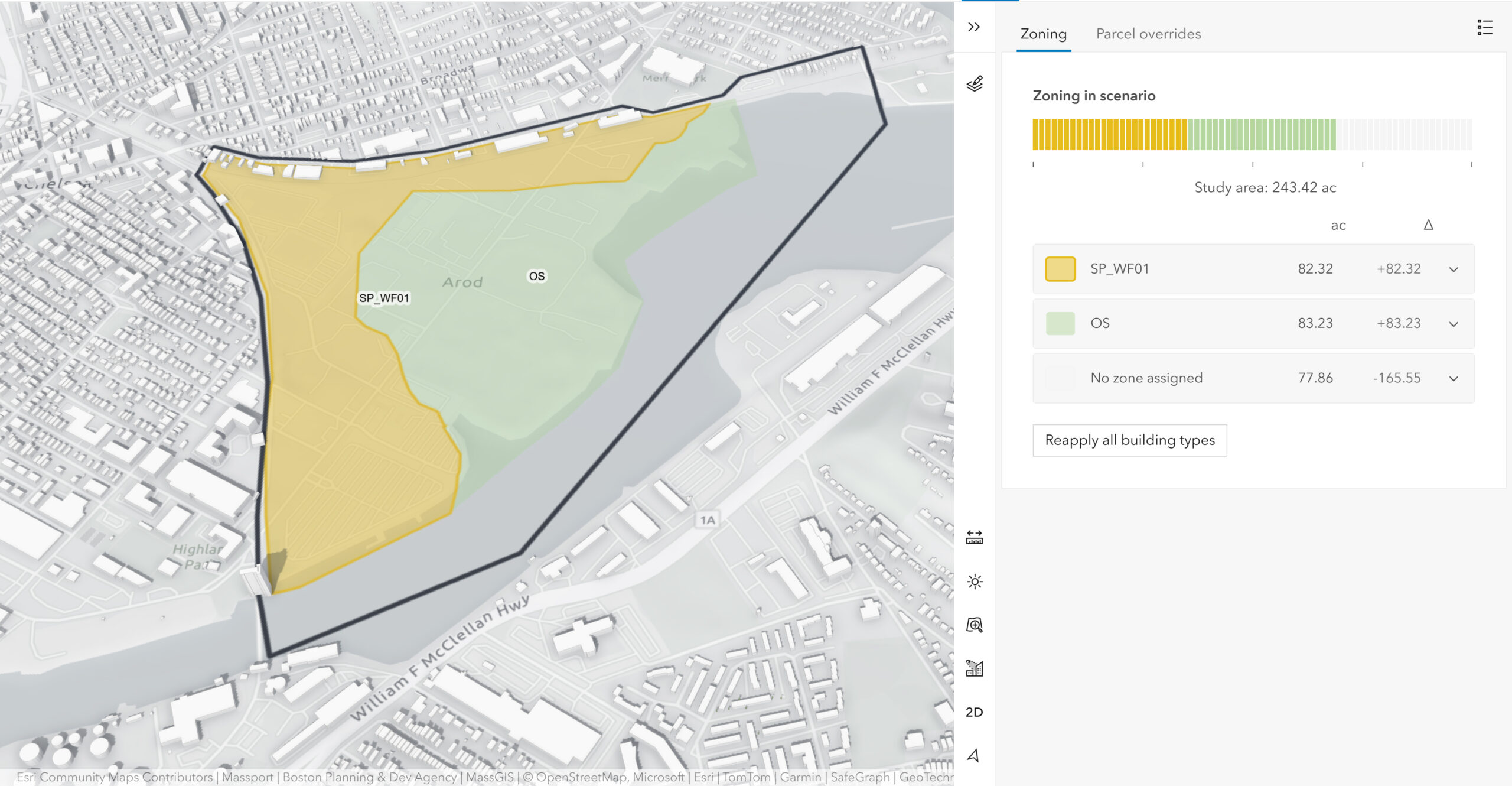
See Work with zoning for more information.
-
Step 2: Define space-use types
Space-use types define how floor area is allocated within a building (for example, residential, office, retail, mixed-use, or industrial).
When you later import the building footprints and generate buildings, Urban uses these space-use types to calculate metrics, visualize land use, and evaluate how well the proposal meets planning objectives.
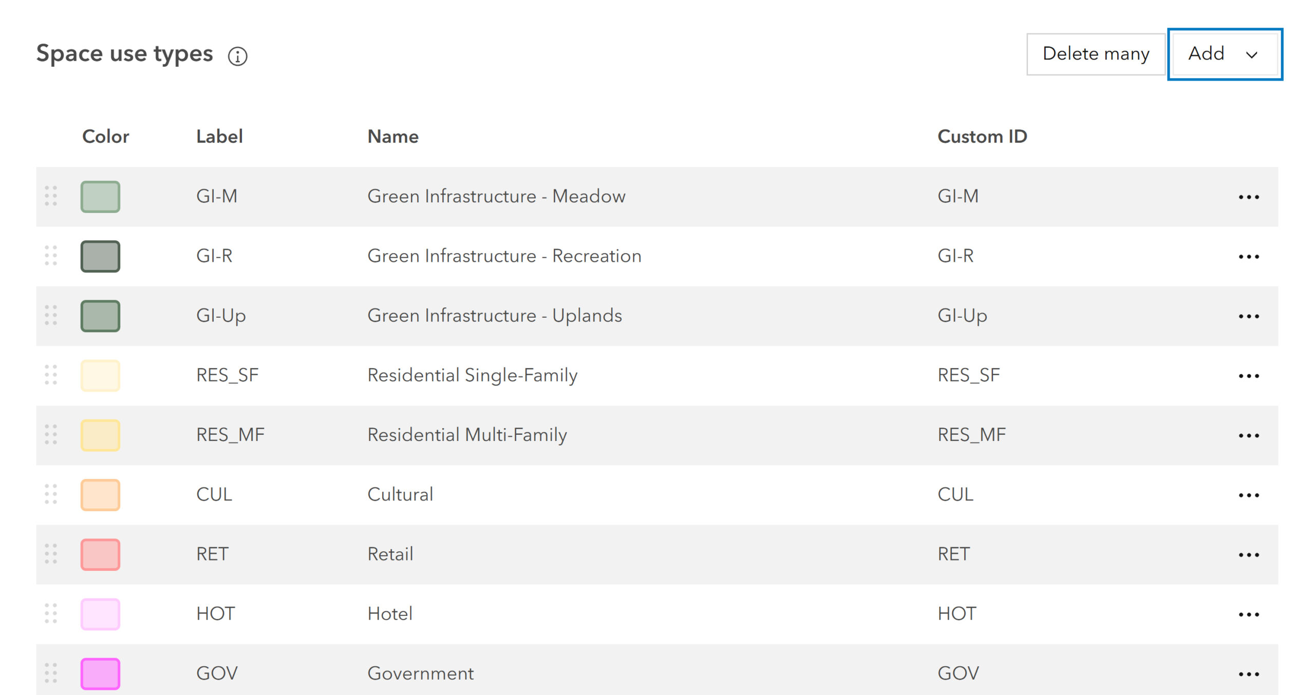
See Work with space-use types for more information.
-
Step 3: Define building types
Building types define the form and characteristics of the buildings that will be generated from the imported footprints.
Use ArcGIS Urban’s predefined building types or create custom ones that reflect your development proposal, then assign them to the footprint layers imported from AutoCAD.
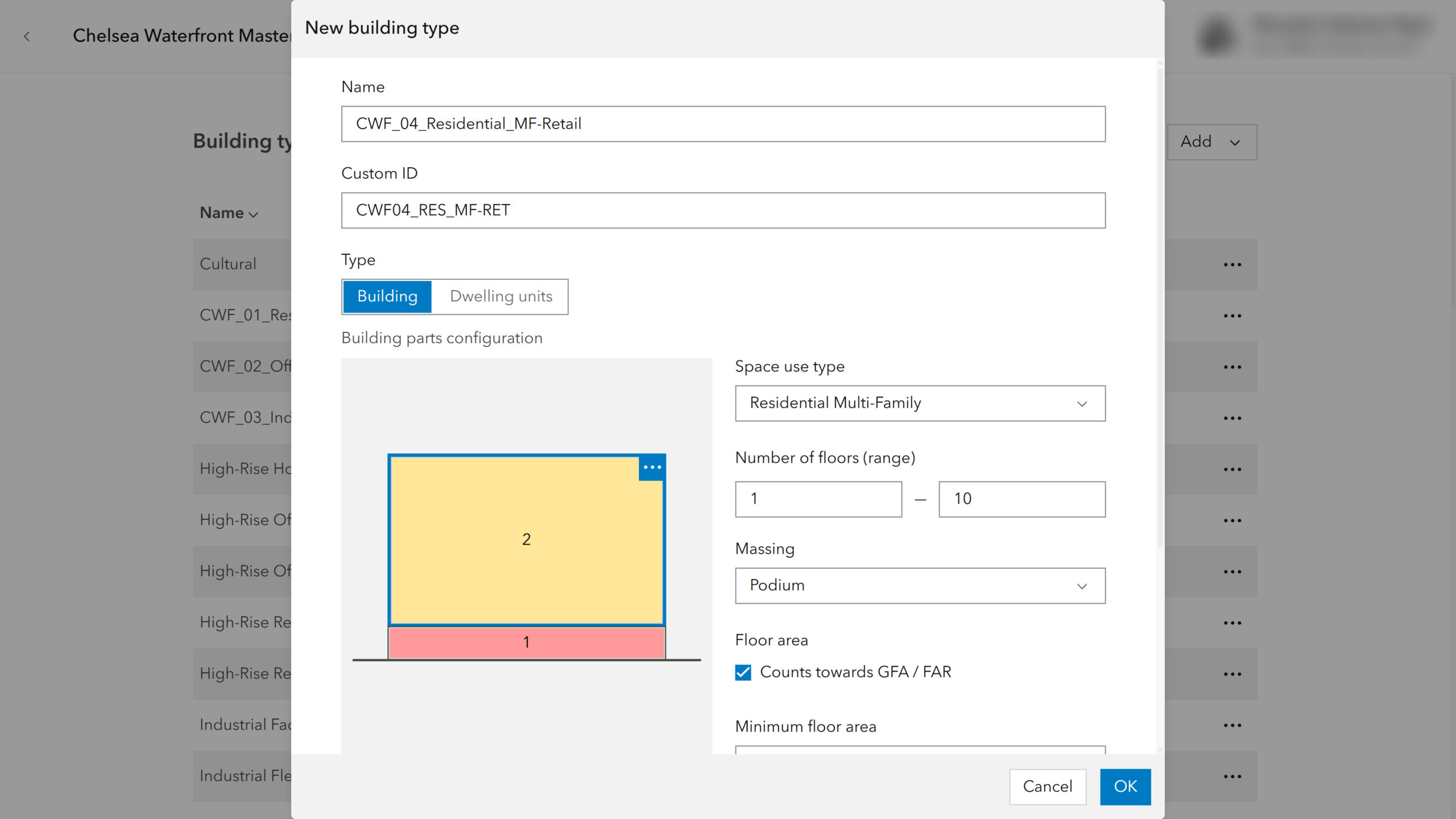
See Work with building types for more information.
-
Step 4: Define metrics
Set up metrics to analyze and compare how different scenarios perform directly in the plan editor dashboard.
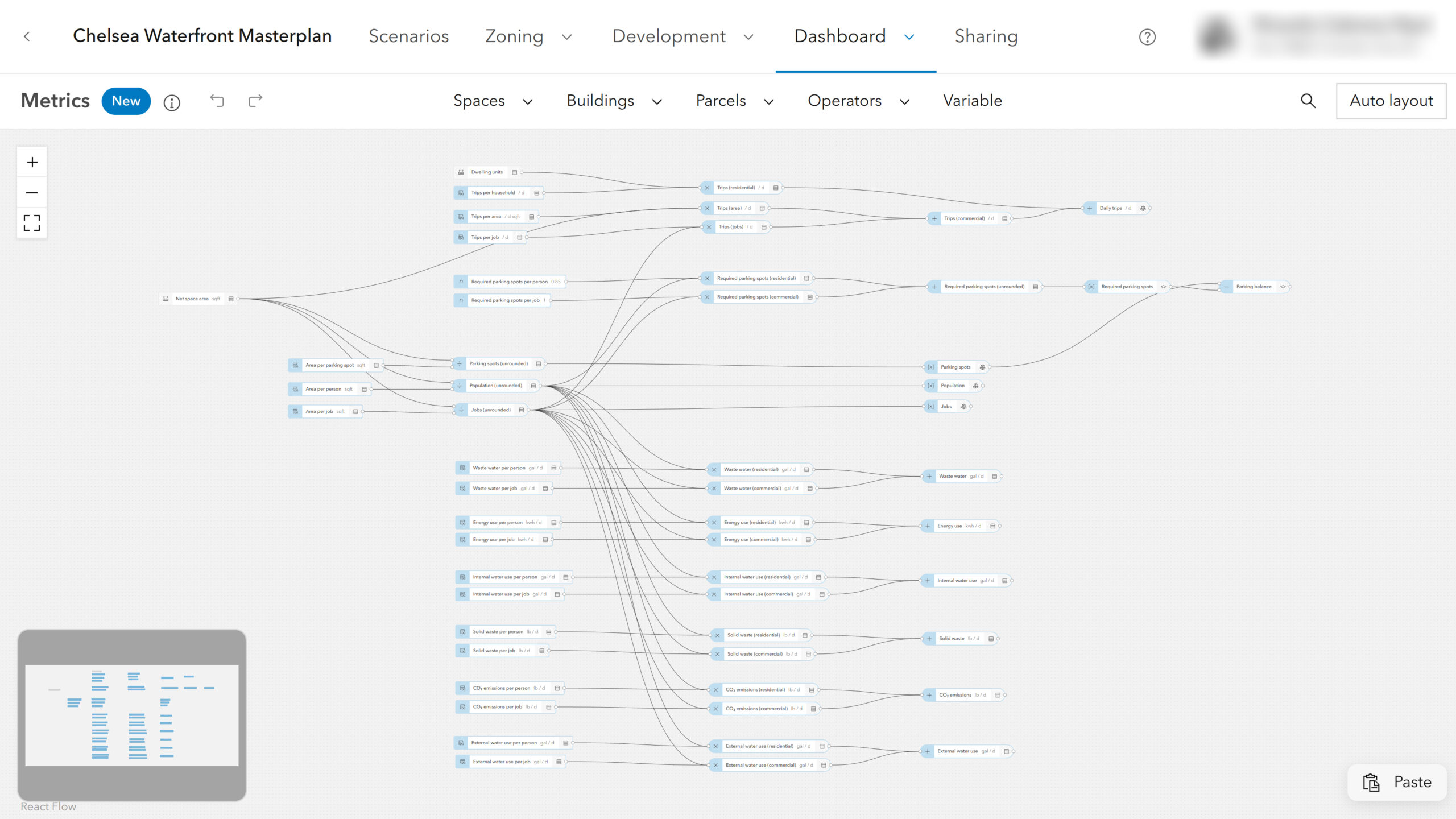
See Configure a metric for more information.
2. Import parcels and footprints
-
Import parcels
Now we can import our parcel polygons from the hosted feature layer and use them as part of the ArcGIS Urban Plan.
The animation below demonstrates the import process.
See Add parcels from a hosted feature layer for more information.

-
Import building footprints
Next, we’ll import the building footprints from the hosted feature layer as a basis for the 3D buildings.
In this case, we need to import the sublayers one at a time and assign a building type to each. This way, all footprints within a sublayer use the same building type.
See Generate buildings from footprints for more information.

3. Refine buildings
The generated volumes are the direct result of applying the building types to the imported footprints.
However, we can use the edit spaces tool to manually refine the massing and change the space-use at floor level.
See Edit building spaces for more information.

4. Final result
Now that we have our buildings in Urban, we can take advantage of its features to refine our plan design.
Let’s look at a few examples:
-
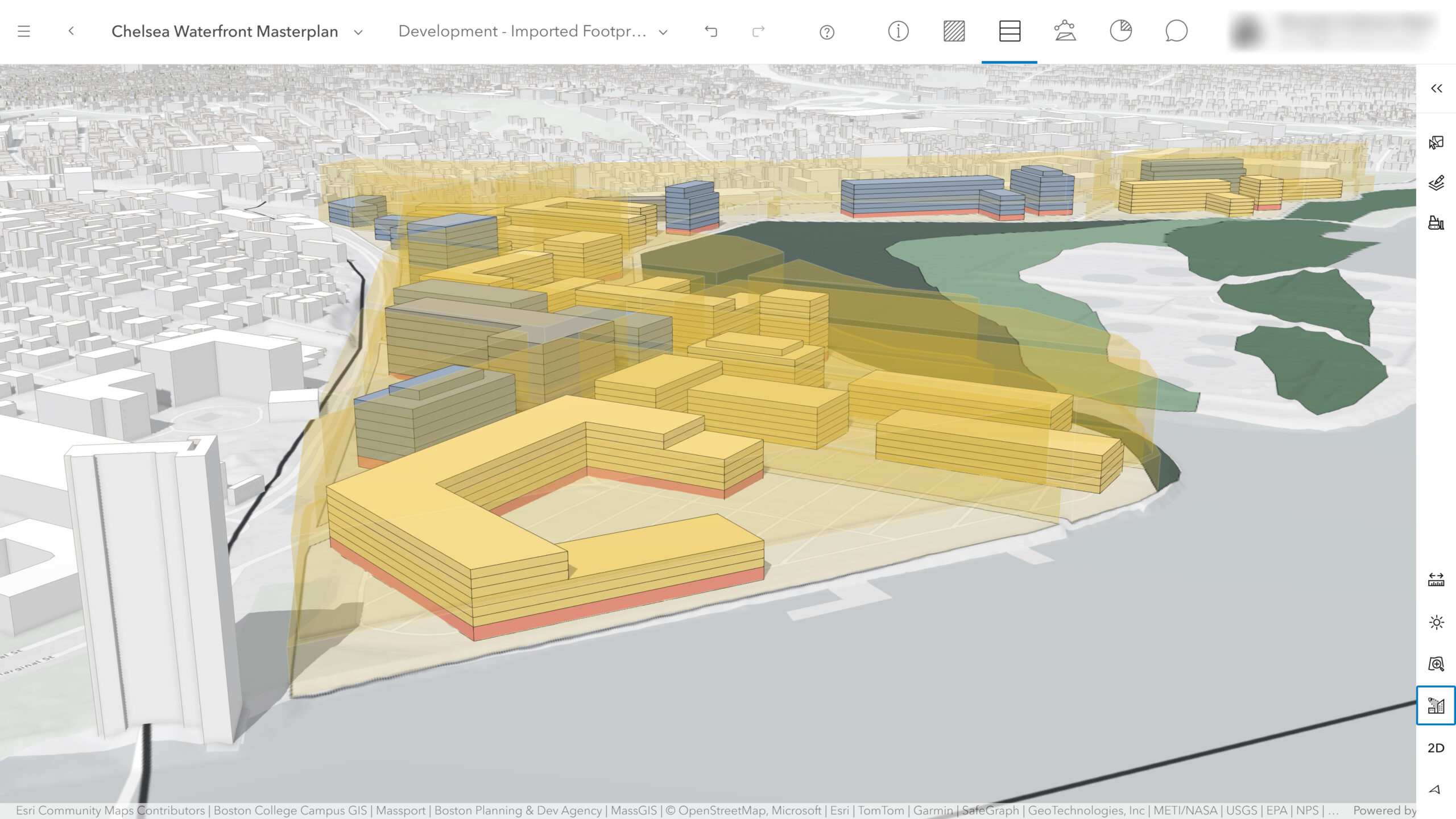
Zoning envelopes
Envelopes display the maximum extent of potential buildings according to the zoning regulation parameters. Urban displays a warning symbol for any building that exceeds the permitted dimensions.
See Envelopes for more information.
-
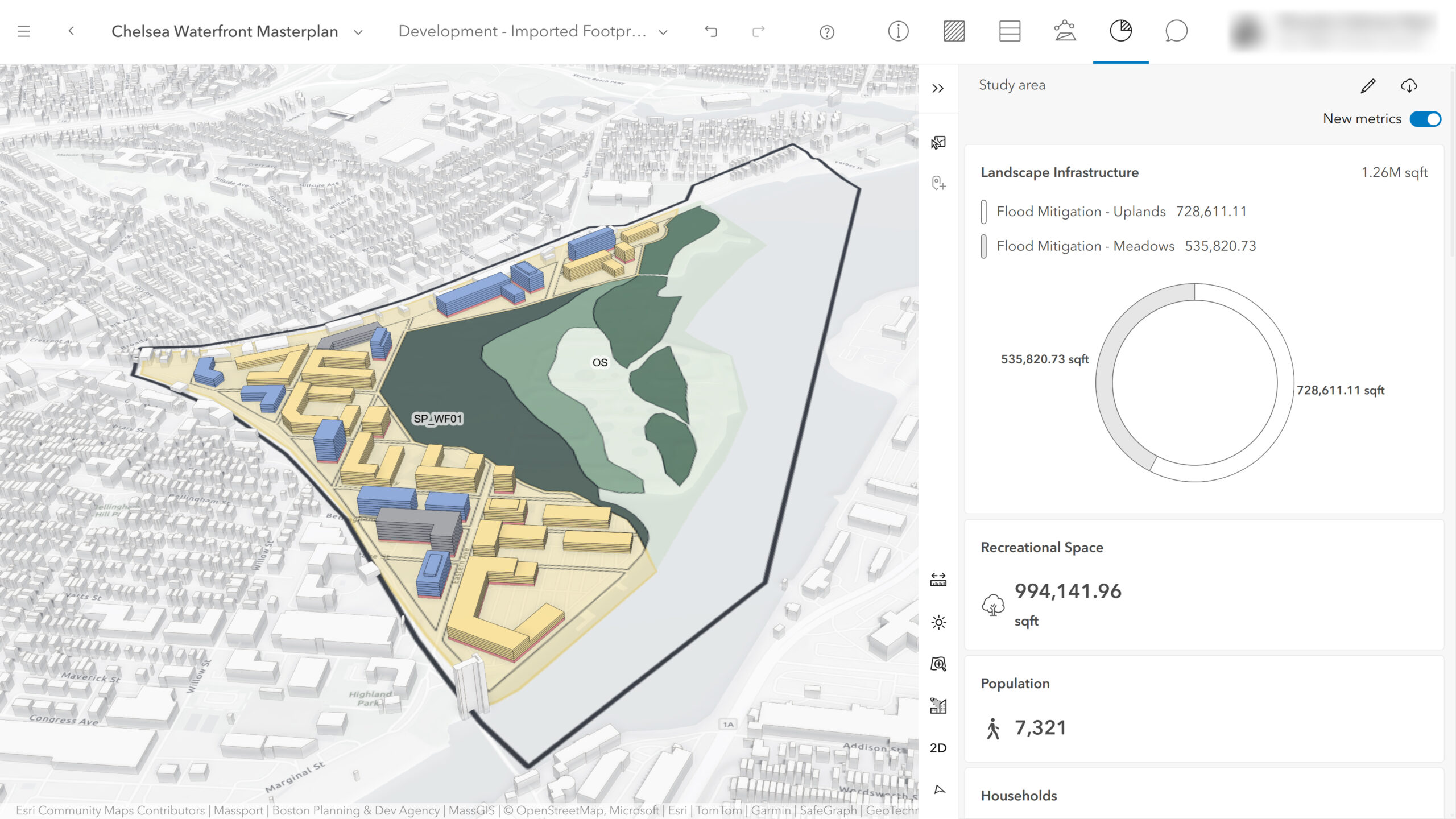
Dashboard metrics
Use the dashboard panel to display key performance indicators based on calculated metrics.
Displaying this information alongside the viewport helps support presentations, team workshops, and real-time analysis of design changes.
See Configure the dashboard for more information.
-
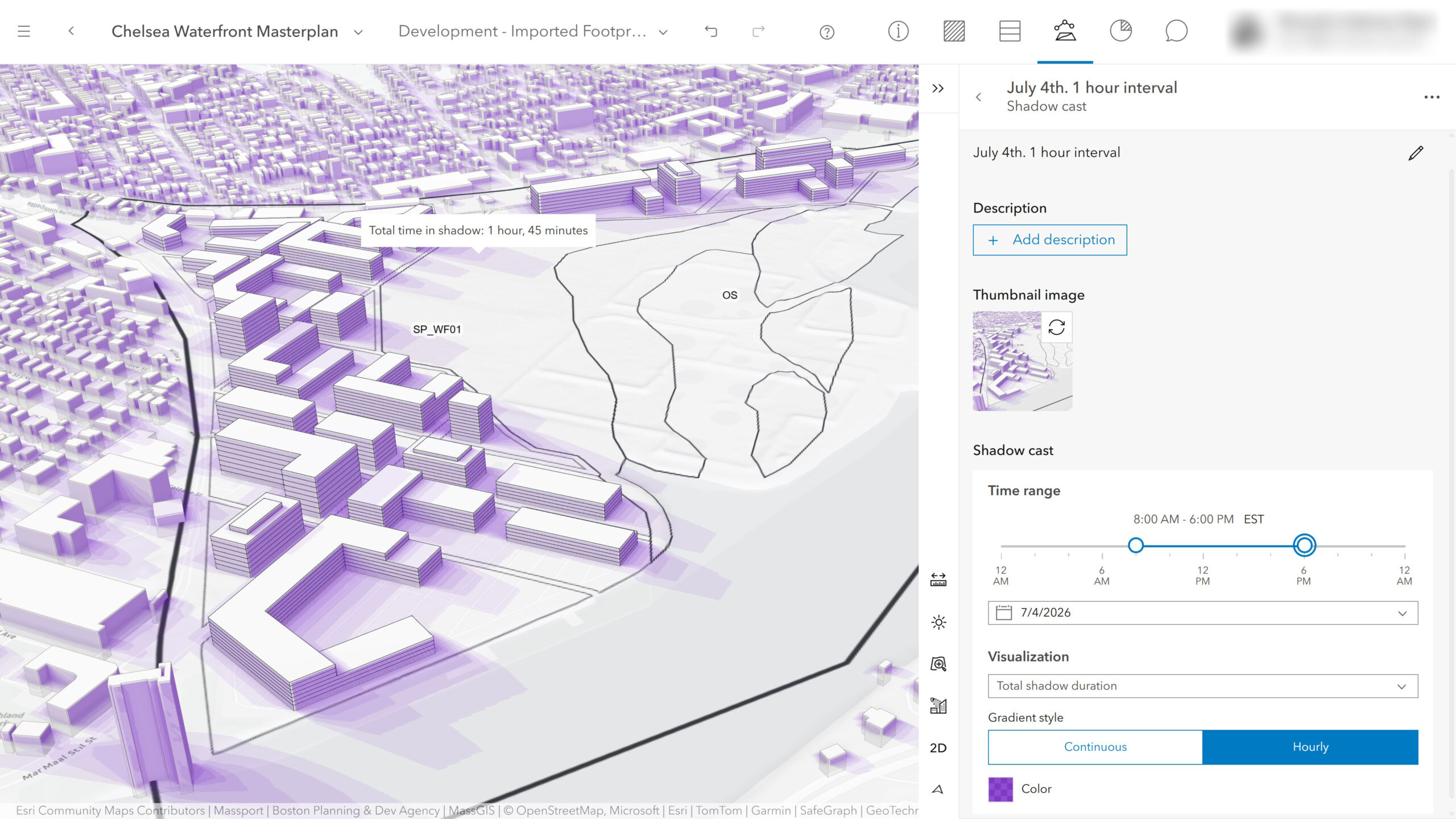
Shadow cast analysis
Urban includes a robust set of analysis tools that support informed decision-making throughout the planning process, including shadow cast, sunlight, line of sight, viewshed, and suitability.
The Shadow Cast Analysis tool helps evaluate the impact of shadows on a specific date across a defined time range.
This makes it easier to understand how proposed developments may affect surrounding areas under varying lighting conditions.
See Work with shadow cast in plans and projects for more information.
These few features highlight just a small part of what ArcGIS Urban can offer to support urban studies.
With many more tools and capabilities available, there is plenty to explore.
Take some time to try ArcGIS Urban for yourself with a 21-day free trial, and see how it can help advance your planning goals.
Summary
If you use ArcGIS Urban and regularly work with AutoCAD drawings, ArcGIS for AutoCAD can help simplify the exchange of data between the two worlds. By enabling a more direct workflow, it reduces the need for manual data handling and makes it easier to keep your planning and design information up to date.
Let us know if you have any feedback or questions by connecting with us on the ArcGIS Urban Esri Community page.

Article Discussion: