In this blog, you will learn about the differences between subnetwork system diagrams and standard diagrams. You will explore the differences in how each diagram is created and updated. You will get recommendations for configuring the subnetwork diagram templates and tips to help you identify when managing subnetwork diagramming using standard diagrams is more suitable than subnetwork system diagrams.
Subnetwork system diagram and standard diagram definitions
Standard diagrams are diagrams that you create and manage on demand starting from the input network features you choose. They represent any part of the network. You can create them for a one-off consultation without storing them in the geodatabase. You can overwrite their content and append new network features to them. You can store a standard diagram as a protected or private diagram to prevent other users from editing or viewing it. You can delete standard diagrams you own and any public diagrams you don’t own at any time.
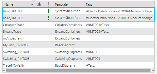
A subnetwork system diagram is a publicly stored diagram that represents an entire subnetwork. Its creation and maintenance are fully managed by the system when you update the related subnetwork. You cannot overwrite subnetwork system content, or append new network features to subnetwork system diagrams. Only the portal utility network owner can delete subnetwork system diagrams. You can identify a subnetwork system diagram among all the diagrams created for a utility network. It appears in the Find Diagrams pane with a green exclamation point in the third column of the diagrams list.
Standard and subnetwork system diagram creation and update
Standard diagrams
Standard diagram creation
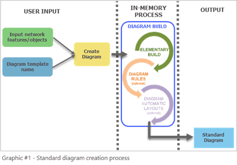
To create a standard diagram, you must first select the initial network features or objects you want to use as input, specify the diagram template to apply, and run the Create Diagram tool. The Create Diagram tool starts from the input network features and objects and runs in memory applying the sequence of diagram rules configured on this diagram template to progressively build the standard diagram content.
Standard diagram update
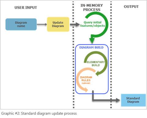
To update a standard diagram, you must run another tool, the Update Diagram tool. The Update Diagram process automatically retrieves the input network features and objects used as input at diagram creation or at its last update. Then, starting from these queried elements, it reruns the sequence of diagram rules set up on the diagram template to update the in-memory diagram graph. By default, the Update Diagram process preserves the diagram layout. This means that the geometry of the diagram features is kept for any diagram feature present in the diagram before and after the update by default. However, any diagram feature added to the diagram during the update process is placed at its geographical position by default. You can run the Update Diagram tool at any time even when your diagram is not dirty.
Subnetwork system diagrams
Subnetwork system diagram creation
Subnetwork system diagrams are created when the Update Subnetwork command runs on a subnetwork for the first time and that subnetwork’s tier is configured with a subnetwork diagram template. When no subnetwork diagram template is defined for a tier, no subnetwork system diagram is created when the subnetwork is updated.
The first time the Update Subnetwork tool runs, the process performs a number of different tasks. It will update the attributes on features that participate in the subnetwork, calculate summaries for the features that participate in the subnetwork, and create a subnetwork line in the SubnetLine feature class. To learn more, read the Update a subnetwork page in the online help.
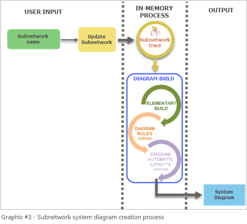
Next, if a subnetwork diagram template exists for the related tier, there is an extra step in the process to create a subnetwork system diagram. During this step, the subnetwork trace runs in-memory and is used as input to build the related subnetwork system diagram. This diagram build process is the same as any standard diagram build process. It consists of applying the sequence of diagram rules configured on the specified subnetwork diagram template to progressively build the system diagram content.
Subnetwork system diagram update
To update a subnetwork system diagram, you must use the Update Subnetwork tool. The update and creation process are the same. The subnetwork system diagram content is fully overwritten starting from the updated subnetwork trace result it builds in memory. The geometry of the diagram features in the updated system diagram is preserved for any diagram feature present in the system diagram before and after the update. However, any diagram features added during the update process are placed at their geographical position.
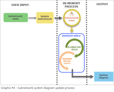
Diagram template setting recommendations for system diagrams
The diagram templates specified as subnetwork diagram templates for tiers must be considered as specific templates. It is recommended that you design your own subnetwork diagram templates and ensure your template settings obey the following design rules:
- Do not set up an Add Connectivity Associations rule when configuring subnetwork system templates since connectivity associations from the subnetworks are already part of the traced subnetwork network elements provided as input for generating subnetwork system diagrams. Addition of this rule will impact performance of the update subnetwork process.
- Since a subnetwork system diagram should accurately represents a subnetwork, avoid configuring its template with diagram rules that could add network elements that belong to other subnetworks when the diagram is built, such as Trace, Spatial Query, and Expand Container rules.
- Consider setting up subnetwork diagram templates with diagram rules that will simplify the subnetwork representation, such as Reduce Junction, Reduce Edge, and Collapse Container rules. Subnetwork system diagrams that strictly represent network elements in the subnetwork don’t provide more value than subnetwork traces do.
- Think about adding diagram layouts on your subnetwork diagram templates so the generated subnetwork system diagrams are automatically laid out during the building process.
To sum up, when designing subnetwork diagram templates, avoid using diagram rules that will slow down the update subnetwork process or expand the diagram to include features from other subnetwork. These rules are listed in the first column in the table below. Instead, consider diagram rules that will help build system diagrams to show simplified and readable representations of subnetworks (the second column in the table below).
| Not recommended for subnetwork diagram template configuration | Recommended for subnetwork diagram template configuration |
| Add Connectivity Associations Rule Add Expand Container Rule Add Expand Container By Attribute Rule Add Spatial Query Rule Add Structural Attachments Rule Add Set Starting Point Rule Add Trace Rule |
Add Diagram Feature Capability By Attribute Rule Add Collapse Container Rule Add Collapse Container By Attribute Rule Add Reduce Junction Rule Add Reduce Junction By Attribute Rule Add Reduce Edge By Attribute Rule Add Start Iteration Rule Add Stop Iteration Rule |
Note: There are three out-of-the-box diagram templates provided by default with the utility network at its creation—Basic, Expand Containers, and Collapse Containers. These diagram templates are generic with definitions that are not specific to any network domain and do not process particular network elements. They are provided to allow you to gain familiarity with network diagrams by generating simple standard diagrams. Nothing prevents you from using these templates as subnetwork diagram templates. However, they are not best suited for use as subnetwork diagram templates. Above all, do not set the Expand Containers template as a subnetwork diagram template since its definition includes an Expand Containers rule that will automatically add content features that can be part of other subnetworks.
Choose standard diagrams or subnetwork system diagrams
You must carefully analyze your needs for subnetwork diagramming before specifying any diagram templates as subnetwork diagram templates for tiers. Consider the following questions:
- Do I need subnetwork diagrams for only a few subnetworks?
- Do I want to have the ability to generate a subnetwork diagram at a time without systematically storing it in the database?
If you answer yes to the above questions, there is no need to set up “system” diagrams that will be automatically created for each subnetwork. Because there is overhead in generating and maintaining subnetwork system diagrams each time you run update subnetwork, only use them when you need them for all subnetworks in a tier.
What if you want a diagram that contains multiple subnetworks? This is another benefit that standard diagrams have over subnetwork system diagrams. If you want to represent a set of specific subnetworks in the same diagram, all the subnetworks in a particular region, or a highly stylized diagram of multiple interconnected subnetworks all in the same diagram, you must use a standard diagram.
In this case, as in the two others above, maintaining such a subnetwork diagram as a standard diagram using the Create Diagram and Update Diagram tools is more suitable than managing a “system” diagram through the subnetwork update process. The best approach is to configure a specific custom diagram template based on a subnetwork trace rule at the beginning of the rule sequence. Then, starting with the controllers related to subnetworks you are interested in as input, you can create the related subnetwork diagrams on demand only when you need it and choose whether to store this diagram.
Conclusion
In this blog, you learned the differences between standard and subnetwork system diagrams, and how to judge the relevance of managing subnetwork diagrams as system or standard diagrams.
In a future post, you will learn what makes standard diagrams and subnetwork system diagrams become inconsistent during typical workflows and how to make these diagrams consistent again.


Article Discussion: