Quality Assurance
In our previous article, we discussed how to use ArcGIS Pro and the Water Distribution Utility Network Foundation to create, manage, and validate subnetworks. If you’re eager to find more content like this, you should explore the reading lists for Water Utilities, Stormwater, and Wastewater as well as these hands-on tutorials related to this article:
- Create and Manage Subnetworks
- Edit and Validate Subnetworks
- Perform Quality Assurance on Subnetworks
In addition to managing the error features reported by the application, there are several other checks that customers often perform as part of their quality assurance program. The issues identified by these checks aren’t considered errors because they are often acceptable and shouldn’t prevent users from completing their work or analyzing data in the system. The following diagram shows a basic quality assurance process used by some customers to identify and manage issues. The workflow ensures each issue is either confirmed and resolved or rejected and marked as being an exception.

The following table provides a summary of recommended quality assurance checks.
| Error Type | Error Description | Resolutions |
| Unknown System Subnetwork | 27—Invalid parent subnetwork discovered during update subnetwork*
|
1. If the affected feature is not active or does not need to participate in a parent subnetwork, then this is not an issue.
2. If the affected feature should participate in a parent subnetwork, then you will need to determine why the parent subnetwork was unable to reach your current device. |
| Unknown Pressure Zone Subnetwork | No error code | 1. If the affected feature is not active or does not need to participate in a subnetwork, then this is not an issue.
2. If the affected feature should participate in a subnetwork, then you should review the associated with your subnetwork to determine why the subnetwork was unable to reach the feature. |
| Inconsistent Parent Subnetworks | 30—Inconsistent parent subnetwork name on multiple parent subnetwork controllers in the same subnetwork discovered during update subnetwork*
|
1. If the affected feature is allowed to participate in multiple parent subnetworks, then this is not an issue.
2. If the affected feature should only participate in a single parent subnetwork, then you will need to determine which system it belongs to and isolate it from the second system. |
*These were subnetwork errors in earlier releases of the software; now they can only be identified through a quality assurance program.
Unknown Pressure Zone Subnetwork
The pressure zone offers the most fundamental way that data in water systems is organized, so in most situations we expect features to participate in a pressure zone. The major exceptions to this rule are the water lines between system controllers and pressure zone controllers, cathodic protection features, or features that are not in service.
You can find example layers that check for these features in the Water Distribution Data Audit map in the Water Distribution Utility Network Foundation. These layers identify the noncathodic features with an unknown pressure zone that are active.

Verify correctness
When you find a feature that does not belong to a subnetwork, the first step is to determine whether it should belong to a subnetwork. When large areas of features are abandoned, you may find that some of the abandoned features didn’t have their lifecycle status set to be abandoned, causing the system to think that these features should be in service. By correcting the lifecycle status of the feature, the feature will no longer require review during your quality assurance process.
Among other common exceptions to this issue are features that participate in a gravity-fed portion of the network. If you have a portion of your network that has its pressure maintained purely by gravity and is not regulated by any sort of valve, storage, supply, or pump, then you will create an exception for that portion of your network.
Identify path to controller
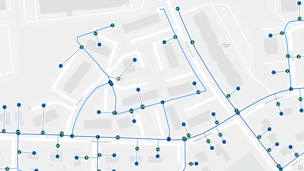
If you’ve found an area that doesn’t belong to a pressure zone, but you believe it should, the first thing you need to determine is how it should be connected. In the example below, we see that there are two areas highlighted in orange that do not have a pressure zone. We suspect the three locations, pointed to with arrows, be causing issues.

The first area is an isolated service line.

When zoomed in, we can see the service line is not connected to the main. This is easily corrected by extending the service line to connect to the fitting on the main. If there wasn’t already a fitting on the main, you would need to add one to avoid getting a missing junction error.

In the second area, we see the system stopping at a check valve.

Because check valves have terminals that only allow water to flow one way, we need to review the terminal connections on each line to verify that they are assigned properly. In our case we can see that the terminals on this check valve are assigned incorrectly or the valve is rotated incorrectly.

If we determine that the valve terminals are incorrect, we use the modify terminal associations tool to assign each pipe to the correct terminal on the check valve. If the valve was incorrectly rotated, we do not change the terminal connections and instead rotate the valve. This also means that we need to continue our investigation for why this area isn’t pressurized.
The third area shows the pressure zone stopping at a closed valve. Although the GIS is the system of record for valve status sometimes it contains data from historical systems that were inaccurate, or changes can be made in the field that aren’t reflected in the GIS. Because of this we occasionally need to verify the status of equipment with engineers or a field crew. If you confirm that the valve is open, then this resolves the issue. If you confirm that the valve is closed, then you will need to explore other pipes and valves in the area to determine how this area is served. An engineer who is familiar with your system should be able to answer this question.

Once you’ve corrected the issue and updated the pressure zone in default, the feature’s subnetwork name will be populated.
Unknown System Subnetwork
We expect every active feature in our water network to participate in either the water system or the cathodic protection system. The ArcGIS Utility Network was originally designed to enforce participation through error features; however, this constraint was relaxed and is something you must check using your quality assurance process. This decision was made because many customers were incrementally loading their data in such a way that some pressure zones were being loaded before their supplies were being loaded. This prevented customers from updating and validating pressure zones.
A common approach for identifying this issue is to validate data using a tool like ArcGIS Data Reviewer, or to have a layer in your map that highlights the features using definition queries. The Water Distribution Utility Network Foundation solution includes an example map, called the Water Distribution Data Audit map, that can be used for quality assurance. The layers in this map use definition queries to show all active, noncathodic equipment that doesn’t have a system subnetwork.

To accurately capture the scenario described above, we need to adjust the query below to ensure that we are only looking at features that belong to a pressure zone and don’t have a system yet.

Verify correctness
If you find one or more complete pressure zones that don’t belong to a system, then you will create an exception for the features in those zones and revisit the features once the appropriate system controllers have been loaded.
In the following example, we have a small pump station the helps fill a storage tower and provides water to a small area. The quality assurance layers show that everything upstream of the pumps doesn’t have a system or pressure zone, but everything downstream of the pumps has a pressure zone but no system. In this case we haven’t yet loaded the records that show how the pump station and storage tower are connected to the entire distribution system, so we create an exception for this area.

Identify path to parent controller
If you’ve found a small area that has a pressure zone but doesn’t participate in a system and you believe it should, then you will need to determine how it is connected to the system. We will use the example from above where we loaded an isolated pump and storage system. Once the rest of the water system has been loaded, we see that there is a transmission main that ends abruptly near the station.

After discussing the system and station with one of our engineers, we have confirmed that this transmission main connects to the station and that there are several additional pipes and fittings we need to model to complete the connection. We add these features, with the appropriate identifiers, then validate our topology and update both the system and pressure zone subnetworks. We can now see that all the features in the area belong to the larger distribution system as well as their original pressure network.
Most networks are designed so that a given feature only belongs to a single system and pressure zone at a given time, and this constraint is enforced by the inconsistent network name error. However, it is not considered an error if a small section of a system or pressure zone is fed by controllers from different networks as long as the controllers can’t connect to one another. Because this is not a typical situation, you should always investigate these areas in your data.

Inconsistent Parent Subnetworks
Most networks are designed so that a given feature only belongs to a single system and pressure zone at a given time, and this constraint is enforced by the inconsistent network name error. However, it is not considered an error if a small section of a system or pressure zone is fed by controllers from different networks as long as the controllers can’t connect to one another. Because this is not a typical situation, you should always investigate these areas in your data.
Verify correctness
If you determine that the areas really are part of two systems or pressure zones, then you can create an exception for this issue.

Rename Parent Subnetwork
If you review the features and determine that the problem is that the two parent systems should be considered the same system, then you should use the modify subnetwork controller tool to update the names of one or both of the subnetworks to match.

In this above example we can see that the area is all part of the same system so we use the modify subnetwork controller pane to rename the controllers for the system.
Isolate from second controller
If the area being supplied by two controllers should not be, then you will want to examine the equipment in the area for correctness.

The first thing you should do is examine the status of the valves in the area to see if there is a valve that could be closed that would isolate the area.

If that doesn’t resolve the issue you should review devices with directional terminals like pumps, pressure valves, and flow valves to ensure that the terminals are correctly assigned. It may be that the terminals on one of these devices is incorrectly assigned, a subnetwork name may have been associated with the wrong terminal.

If neither of these options resolves the issue you should consult an engineer or planner to determine whether this situation is correct or whether there is additional information not captured in the GIS.
Next Steps?
Now that you’ve read all three blogs in this series, you are well-equipped to create and manage your own subnetworks! We recommend that you keep a link to these blogs handy in case you need to refer back to any of the examples or screenshots provided. Fortunately, all of these articles and a series of error reference guides can be found in an article in the Utility Network section of Esri Community. We recommend that you use the ArcGIS Utility Network community page to ask any questions you may have—or answer others’ questions—about the utility network so that we can all be successful together!
If you’re interested in more content like this, I recommend you check out the Learn ArcGIS Utility Network for Water utilities and Learn ArcGIS Utility Network for Sewer and Stormwater learning series as well as these hands-on tutorials related to this article:


Commenting is not enabled for this article.