|
Changing Feature Symbolization
Three ArcXML renderer elements provide information
on how to symbolize point, line, and polygon data. Feature data
is rendered based on the following elements:
- SIMPLERENDERER draws all features using the same symbology,
- VALUEMAPRENDERER renders features based on values in a tabular
field,
- and SCALEDEPENDENTRENDERER only draws features within a specified
scale range.
Multiple renderer elements included in a single
layer must be enclosed by a GROUPRENDERER element. Each renderer
element contains a child symbol element that defines how the feature
should be rendered.
There are many types of symbol elements. Symbol
elements are specific to the type of feature being rendered. For
example, the SIMPLEMARKERSYMBOL element only defines rendering for
point features. Although the HASHLINESYMBOL element used to define
line features representing railroads is available in Author, attributes
such as width and interval can be manually added to the map configuration
file to override default attribute values for this element and redefine
how a HASHLINESYMBOL line is drawn.
Feature symbolization can also be based on a value
in a field. The VALUEMAPRENDERER element can classify features in
a layer according to values in a field. Based on that classification,
it renders data using graduated or unique symbols.
EXACT, RANGE, and OTHER, the three child elements
used with the VALUEMAPRENDERER, specify the values to be symbolized.
Using the EXACT element renders the feature with a particular value
while RANGE renders features from a range of values. The OTHER element
renders features that do not have a specified value. For example,
a specific true type marker symbol can be set for capital cities,
and all other cities will be rendered using a simple marker symbol.
Some symbol elements, such as the GRADIENTFILLSYMBOL
and TRUETYPEMARKERSYMBOL elements, are not available in the Author
interface and can only be accessed by using ArcXML. With ArcXML,
the many point symbols available from Esri can be used by ArcIMS.
Labeling Features
Label properties are defined in two label renderer
elements--SIMPLELABELRENDERER and VALUEMAPLABELRENDERER. The former
sets the same labeling properties for all features; the latter defines
label properties based on values in a tabular database. Author can
set the label properties of layers, such as label field, label position,
and font characteristics. Only one field can be identified for labeling
in the Layer Properties dialog box. Author also adds two child symbol
elements to the label renderer element--TEXTSYMBOL for text
labels and SHIELDSYMBOL for highway shield labels.
Manually editing the map configuration file by
adding other child symbol elements within a label renderer element
and modifying the attributes for those elements offer a greater
range of labeling options. For example, the CALLOUTMARKERSYMBOL
element, which adds a callout box and arrow to label a feature,
has attributes that can define the font properties and the callout
box symbology including the length of the arrow.
Attributes to label renderer elements can change
the placement and frequency of labels. To concatenate two or more
label fields, listing field attributes in order, separated by a
space, allows labeling using multiple fields when using the SIMPLELABELRENDERER
element. Use the same procedure to concatenate labels using the
labelfield attribute of the VALUEMAPLABELRENDERER element.
The labelpriorities attribute for point features
positions labels relative to a point based on specified preferences.
The labelbufferratio attribute creates a buffer around each label
so that other labels cannot be placed closer than a specified distance.
The howmanylabels attribute controls the number of labels drawn--one
per feature shape, one per feature part, or one per feature name.
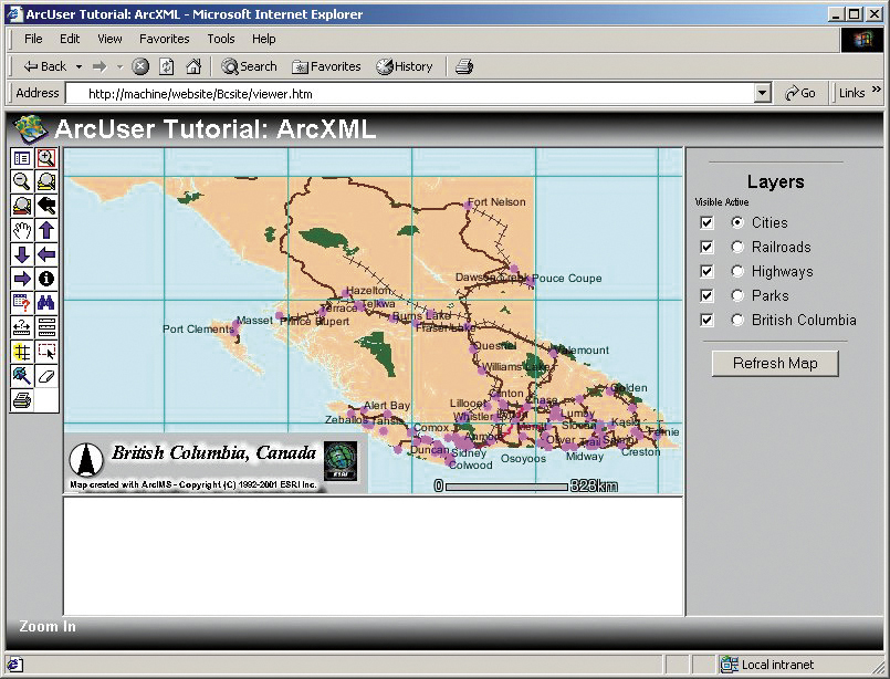
Manipulating Graphic Elements
Specifying acetate for the type attribute of a
LAYER element adds graphics on top of the map. An acetate layer,
generated for each image map for an HTML Viewer, adds graphics in
a map that are separate from the data layers. OBJECT child elements
included in the default acetate layer are the north arrow, scale
bar, and copyright text. New OBJECT elements can be added to the
acetate layer by adding a new LAYER element to the map configuration
file.
 |
| Specifying acetate for the type attribute
of a LAYER element adds graphics on top of the map. |
Each new LAYER element must have the type attribute
set to acetate. Inside the LAYER element are one or many child OBJECT
elements. Each OBJECT element requires a units attribute set to
pixel or database. If the units attribute is set to pixel, the object
will be positioned based on the pixel coordinates of the image based
on an origin set at the bottom left corner of the map. If the units
attribute is set to database, the object is positioned using the
map coordinates of the MapService.
In addition to the north arrow and scale bar, a
shape object (point, line, or polygon) or a text object can be added
to an acetate layer allowing an item such as a title block, composed
of a title and a corporate logo encompassed by a rectangle, to be
added within the new LAYER element. An image is added with a RASTERMARKERSYMBOL
element inside a POINT object element. The POLYGON element can contain
a SIMPLEPOLYGONSYMBOL element with the overlap attribute set to
false so labels will not overlap the acetate layer box. Objects,
such as LINE object elements that replicate map coordinate grid
lines, can be added to the map display.
Continued on page 3
|