An indoor GIS can help organizations bring their facilities to life through rich, floor-aware maps that transform complex indoor environments into clear, navigable digital twins. By modeling buildings, assets, and routable pathways with precision, ArcGIS Indoors provides a comprehensive framework for visualization, situational awareness, and spatial decision making inside facilities.
Building on this foundation, indoor routing enables seamless wayfinding and turn-by-turn directions across and between floors and buildings, supporting everything from navigation to operational workflows and emergency response.
Ensuring accurate indoor routing, however, starts long before we support one of the key patterns of use — it begins with data validation. At the core of that quality assurance effort is one critical principle: routing is only as accurate as the geometry behind it. For ArcGIS Indoors, high-quality network geometry is essential; even small vertical inaccuracies can lead to incorrect or confusing directions.
Many of the common errors that may disrupt your indoor routing network can be difficult to find or catch with just visual review. This is where ArcGIS Data Reviewer comes into play. Data Reviewer provides a library of automated data checks that support consistent detection, management, and reporting of errors in your data. Data Reviewer’s automated checks to detect vertical inconsistencies, disconnected pathways, dangles, and unsupported geometry, helping teams validate both Z-values and network connectivity. These automated checks support multiple workflows, allowing you to run ad hoc validation with the Run Data Checks, while also enabling you to persist these configured checks as attribute rules for ongoing, automated quality control.
When creating indoor routing networks, the Generate Indoor Network Features tool does a great job building the horizontal and vertical floor transitions, however, there is often some manual clean up that is still required. There are several common errors that I often run into and in this blog, I’ll share a few of my techniques used for ensuring my data meets the requirements for indoor networks. These Data Reviewer checks will help you to conduct effective quality assurance on indoor networks to ensure routing is accurate, reliable, and ready for real world use.
Verifying Network Verticality
When creating and editing a Network Dataset for routing in ArcGIS Indoors, it is essential to verify that the pathways and transitions in the ArcGIS Information Model are drawn not only at the correct horizontal location (X,Y coordinates), but also at the correct elevation value (Z coordinate). This can be done using the Generate Indoor Network Features (Indoors) geoprocessing tool following this workflow. It is important to note that the underlying assumption is that z-values are measured relative to ground level, which is assigned a value of zero.
When users generate a route, the request passes the three-dimensional geometry to the route service to generate an output. Since routing relies solely on geometry, it will draw incorrect routes if it is passed incorrect geometries. Therefore, it is critical to verify that pathways are drawn correctly in all three dimensions to ensure that the output route is accurate.
The first step of testing a newly created routing network is to verify the Pathways are at the correct Z levels. Otherwise, when a user generates a route, the Route service may unintentionally pick up a pathway that is on an incorrect level and output nonsensical directions.
3D Visual Inspection of Pathways
One of the most common reasons for pathways to be at incorrect Z-values is improper manual drawing of new pathways. It is very common to not set a z-plane when editing or snap features to incorrect floors (especially when editing in 2D), which causes drawn paths to be at incorrect Z-levels.
The quickest and easiest way to check Pathway Z-values is to do an initial visual inspection of the network in an ArcGIS Pro scene:
- Add the Pathways and Transitions feature classes to a new local scene
- Turn off the default elevation surface, unless the network is drawn at absolute elevation
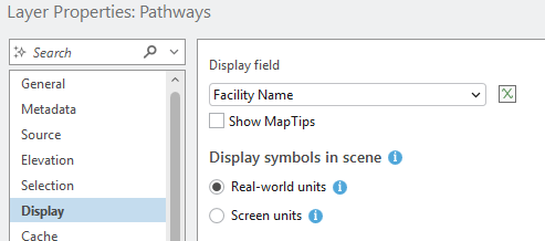
- To best visualize the network features, update the layer Display Properties to display symbols in real-world units (see image 1)
- Update the symbology to preferred symbol type, size, and color(s)
- Recommended Symbol Type: Tube
- Recommended Pathway Symbology: Unique Values by Vertical Order
- Recommended Transition Symbology: Unique Values by Transition Type
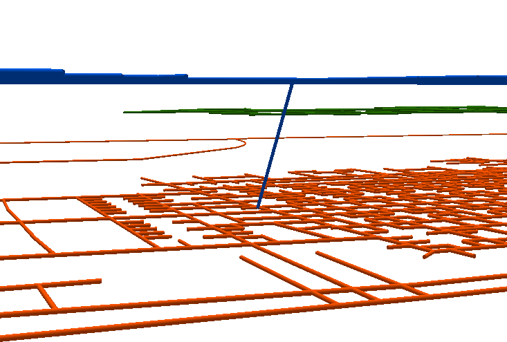
- Orient the camera to a near ground-level perspective
Once the camera is oriented, any extreme elevation changes will be very apparent.
Adjacent Vertex Elevation Change
While the previous example showed a visually clear example of a point located on the incorrect floor, often, z-value errors are more subtle and less visually apparent. These less extreme errors can still impact indoor route performance. To identify more subtle unintended elevation changes, Data Reviewer’s Adjacent Vertex Elevation Change check can locate elevation changes along a line. While there are exceptions where this is correct (ex. a ramp that is not a transition between two floors), generally, all lines on a given level should share a constant Z-value. Running the tool is as simple as defining the Pathways as the Input Feature, setting the acceptable elevation tolerance and clicking ‘Run’.
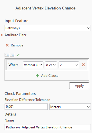
It is recommended to use the smallest possible tolerance to ensure the most consistent routing network.
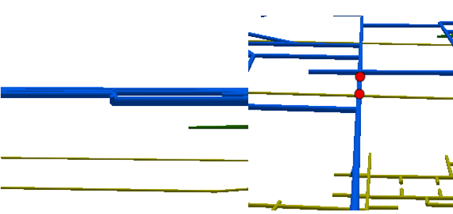
In the before and after images above, the change in elevation is subtle and not obvious until it is highlighted by the results of running the Adjacent Vertex Elevation Change in Data Reviewer. Relying soley on visual inspection would have likely missed detecting this error.
Evaluate Z Values
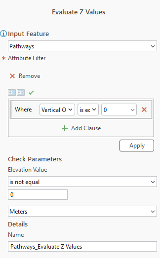
To further verify Z-values, Data Reviewer’s Evaluate Z Values check can be used as well. It compares the Z-values of the input features with the expression defined when configuring the tool. For example, all ground level pathways presumably have a Z-value of 0, so an expression where the Elevation Value does not equal 0 would highlight any verticies that are not a z-value of 0.
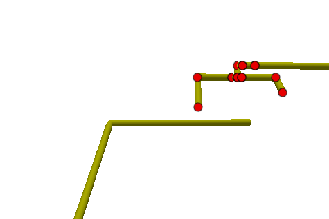
This check can also be used to evaluate Transitions to ensure that all verticies are between the Z-values of the levels that the transition traverses. For example, when editing a stairwell, errors like accidently snapping a pathway to the wrong level can easily happen. This check helps ensure that all of the stairs from level 1 to level 2 have Z-values between 0 and 4.5 meters and can identify an errant vertex snapped to a pathway on level 3 at 9 meters.
Identifying False Errors
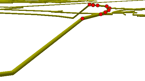
Using the workflows above, it is possible to have false errors identified in the output. Usually, these false positives are identified when a level has intra-level ramps or stairs. When modeling the routing network, the Pathways should be consistent with how the Units and Levels are modeled. For example, if the corridor with the ramp is on a constant Z-plane, then the corresponding pathways should be on the same Z-plane. If the corridor is drawn with the elevation change included, the pathways should mirror this change when drawn.
Updating Z-Values for Network Features
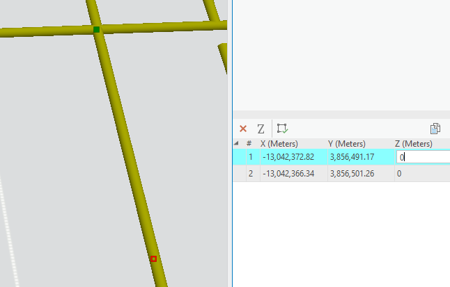
Once errors are identified, the Z-values can be updated to fix the routing network. For smaller, more isolated errors, it is most efficient to select the incorrect segment and manually edit the vertices using the Edit Vertices tool in the Edit ribbon.
For larger, more systemic errors (ex. most of a floor is drawn on the wrong Z-plane) there is a workflow for bulk resetting pathways (usually done by level) to a desired Z-value by snapping the pathways to a surface:
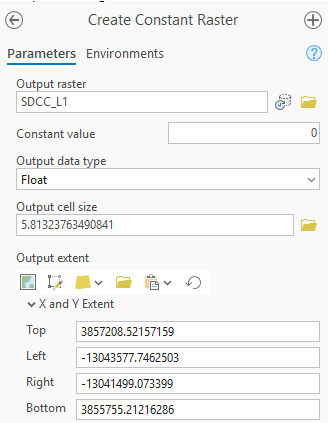
- Run the ‘Create Constant Raster’ geoprocessing tool
- Constant Value equals the Z-value for the corresponding Level
- Set the output data type as Float
- Zoom out to see all data and set Output Extent to Current Visible Extent
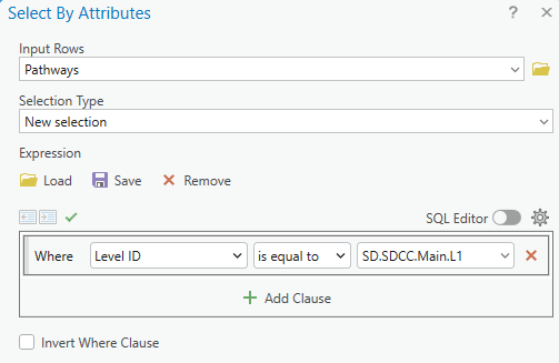
- Select the Pathways to be snapped to the desired Z-value
- This can either be selecting all paths on a level or a subset of paths that need to be fixed.
- Run the ‘Update Feature Z’ geoprocessing tool
- Input Features are the selected pathways to be updated
- Input Surface is the surface raster that was created in Step 1
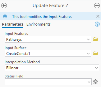
It is most common to repeat this workflow for each level, vertical order, or subset of errors as necessary.
Verifying Network Connectivity
Once the vertical integrity of the routing network is verified, the next step is to verify that the routing network is connected as expected. Common errors include:
- Pathways that are completely dissociated from the rest of the routing network
- Pathways that are not quite snapped together (causing a disconnection)
- Pathways that intersect geometrically, but do not have a vertex at the intersection point.
All of these situations would cause potentially inaccurate routes to be generated or complete routing failures altogether.
The next step in testing an Indoors routing network is to verify the connectivity of the routing network itself. Data Reviewer provides multiple checks to do an initial review of the pathway data, which we’ll take a look at in the following section.
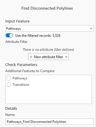
Find Disconnected Polylines
A common error that occurs when editing a routing network is when pathways or transitions are not connected to the network. The Find Disconnected Polylines check in Data Reviewer can be configured to find disconnected pathways or transitions that are completely removed from the routing network.
Find Dangles
It is very common when editing the routing network to not snap the pathways correctly, leading to possible disconnections in the network. The Find Dangles check can identify features where this is a potential issue.
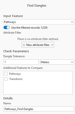
To limit the number of false positives identified by the tool, it is recommended to keep the tolerance value to one meter or less. It is important to note that the tolerance value being too small can cause the tool to potentially miss dangles that are actually data errors.
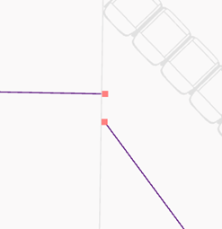
The image above shows an example of two features identified as errors by the tool. Because these paths are not connected, a generated route would not be able to traverse this intended line.
Nonlinear Segments
The Nonlinear Segments check identifies segments that are drawn as true curves. This is an essential check to run as routing networks do not support true curves, which are features that instead of being lines made up of straight segments between vertices, are instead made up of a few where the segments between have a defined radius and angle.
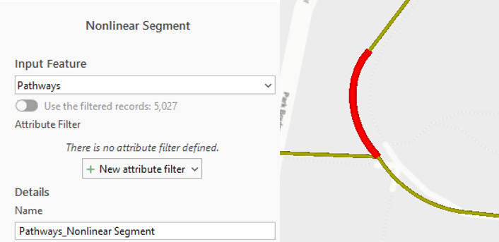
This is a very common error when manually editing the routing network to model curves, especially when digitizing sidewalk centerlines.
Service Area Analysis
Once checks for basic geometry errors are complete and resolved, users should check for connectivity directly using network analysis tools. Service Areas are best positioned to do this because it calculates the time it takes to get to any given point on a network. There are two core benefits to this: paths not connected do not get highlighted at all, and adjacent paths with drastic differences in route time indicate another possible connectivity error. This analysis can be done in a few steps:
- Add the Network Dataset item to the scene as well as a new Service Area analysis group layer
- Configure the Service Analysis to have one cutoff that will encompass the entire network
- Configure the Service Analysis to output lines instead of the default polygons

- Add a Facility to the network
- There is no requirement on where the facility is placed, as long as it is snapped to the network.
- Run the Service Area analysis and symbolize the Lines layer to be easily visible
- Symbolize the lines based on the ToCumul_WalkTime field
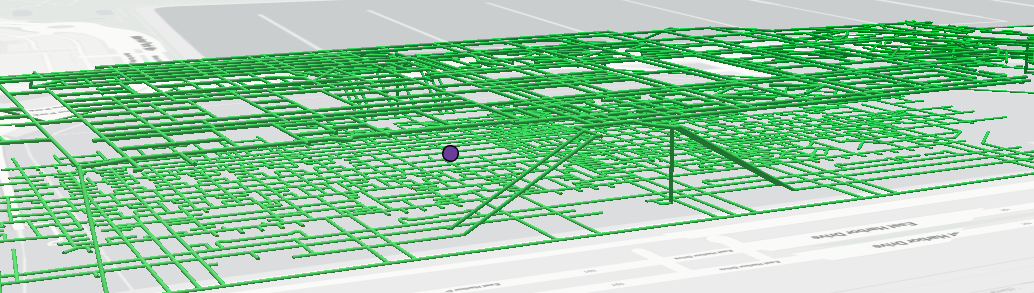
Once the analysis is completed, any segment that has not been highlighted is disconnected from the network.
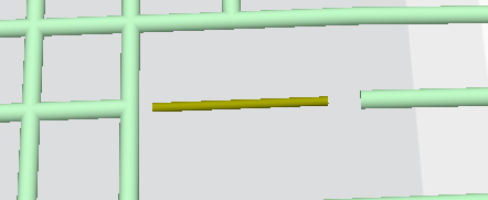
In the image above, the yellow segment is an example of a pathway that is disconnected from the network due to the path segment not being properly snapped to the rest of the network.
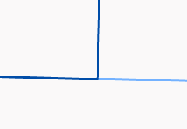
In the image above, note the sharp contrast of color at the identified intersection. Since both paths are highlighted, they are connected to the network, but the sharp change in color implies that the connection at this point is not traversable. It is possible for this to be a false positive, most common in workflows utilizing one-way routes (ex. routing through a security checkpoint).
Once you have created the indoor routable network, you can use it to generate turn-by-turn directions in Indoors Viewer and Indoors Mobile apps.
Accurate indoor routing is hardly ever accidental, but rather the result of thorough quality assurance. In indoor spaces, even minor vertical inconsistencies or subtle connectivity gaps can lead to confusing directions, failed routes, or unreliable wayfinding experiences. By combining visual inspection with automated data checks in ArcGIS Data Reviewer, organizations can proactively and efficiently detect and correct errors before they impact end users, allowing for accurate, reliable routing.
For more information, visit the ArcGIS Indoors and ArcGIS Data Reviewer page, and explore the full range of data quality checks.

Article Discussion: