Autodesk® Civil 3D® is a civil engineering design and documentation software that is widely used in infrastructure projects. Designers create and modify design elements such as surfaces, alignments, and profiles in a parametric and associative manner using an integrated design environment. Changes made to one part of the design automatically update related elements, saving time and reducing errors.
Built infrastructure projects typically require modification to the existing ground.
Designers use Civil 3D to model proposed (design) surfaces, which are constituents of infrastructure components such as corridors, culverts, and grading. Presented in the following is one of multiple approaches for your GIS team to incorporate surfaces from Civil 3D into ArcGIS Pro scenes. The presented approach leverages the Topography (multipatch) feature class and generation of raster layers for visualizing proposed ground in context with existing ground, as well as built underground components. Further, the approach discussed here is robust to project phases where the proposed surface interior undergoes frequent changes. For example, the raster layers generated as described below uphold the border of the proposed surface. In these instances, updates are only needed for the Topography feature class.
Existing ground in ArcGIS Pro scenes
Existing ground in ArcGIS Pro scenes derives from the basemap, for example, the World Elevation 3D layer. When surface models for proposed ground, such as those from Civil 3D, are added to scenes in ArcGIS Pro, the elevation surface that represents existing ground takes precedence. This can obscure portions of the proposed surface located below the existing ground surface.
One way to visualize elements of the proposed surface is to hide the elevation surface layer that represents the existing ground. Without having the contextual reference of the existing ground, though, navigating the scene becomes less accurate and less meaningful. Further, other features rendered in the scene can appear as detached from the ground (as if floating), particularly if the project site lies in an area with pronounced elevation changes.
Visualize existing and proposed ground together with built underground components
Consider instead the following approach for crafting ArcGIS Pro scenes when working with Civil 3D ground surfaces. This approach harmonizes differences between elevation surface layers for existing and proposed ground, and additionally, enables visualization of built components located beneath the proposed ground surface. Starting with a scene in ArcGIS Pro that contains existing ground and built underground components, the approach consists of the following steps:
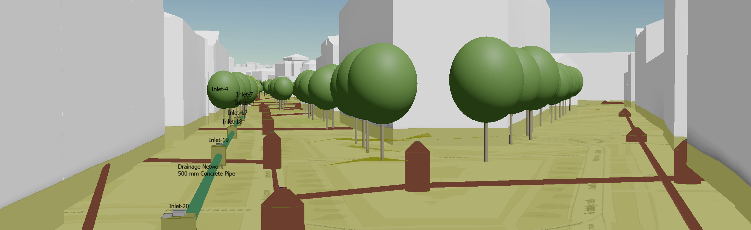
- Add the Civil 3D surface as multipatch features to the ArcGIS Pro scene using the Topography feature class.
- Create a raster layer using the Multipatch to Raster geoprocessing tool.
- Create a second raster layer, using the Raster Calculator geoprocessing tool, and position the raster layer below the built underground components of interest.
- Add the raster layer from step 3 to the top of the Elevation Layers group.
- Increase the transparency of the multipatch features representing the proposed surface.
In this way, the existing ground, proposed ground, and the built components located beneath the proposed ground surface are all included in the scene for visualization.
Add the Civil 3D surface to the scene as multipatch features
In ArcGIS Pro, surfaces created in Civil 3D are collected into the Topography listing and represented as a multipatch feature class. Complete the following steps to add the surface to the scene:
- Browse to the Catalog pane and expand the content listings of the Civil 3D DWG file that contains the surface model of interest.
Included among the listings is a feature class named Topography. - Right-click the Topography feature class and add the surface (as a layer of multipatch features) to the scene.
- If the Topography feature class contains multiple surfaces, apply a filter to the newly added feature layer to isolate the surface of interest.
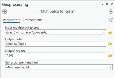
Create a raster layer using the Multipatch to Raster tool
To create a raster layer using the Multipatch to Raster tool, complete the following steps:
- Browse to the Geoprocessing pane and search for Multipatch to Raster.
- For the Input multipatch features parameter, select the feature layer representing the proposed surface.
- Supply a name for the Output raster parameter.
- Specify the Output Cell Size value, where smaller values produce higher-density raster grids.
- For Cell assignment method, select Minimum height.
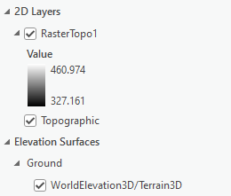
- Click Run to produce the raster layer, which will be automatically added to under the 2D layers of the scene.
Create a second raster layer using Raster Calculator
Next, you will generate a second raster layer, which is needed to modify the existing elevation surfaces in the scene and expose built underground components.
- From the Geoprocessing pane, search for the Raster Calculator geoprocessing tool.
- Use this tool to produce a copy of the raster representation of the proposed ground surface that is translated downward . The extent of the downward translation depends on the depth of the built underground components relative to the proposed ground surface.
For example, to produce a raster layer that is translated downward by 12 units, populate the required inputs to the Raster Calculator tool. In the Rasters column, double-click the raster layer generated from step 2. Then, from the Tools column, double-click the subtraction operator.
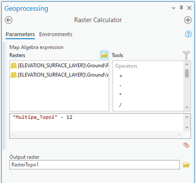
3. Supply a name for the Output raster parameter and click Run.
The newly created raster, with the downward translation applied, will automatically be added to the scene under the 2D Layers group.
Add the second raster layer to the elevation surfaces
As the next step, you will modify the definition of ground for the scene.
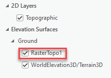
- Browse to the Contents pane, and drag the downward-translated raster layer from the 2D Layers group to the Ground group under Elevation Surfaces, as shown below.
- Ensure that the layer is ordered first in the Ground group so that precedence is given to the raster layer rather than the WorldElevation3D/Terrain3D
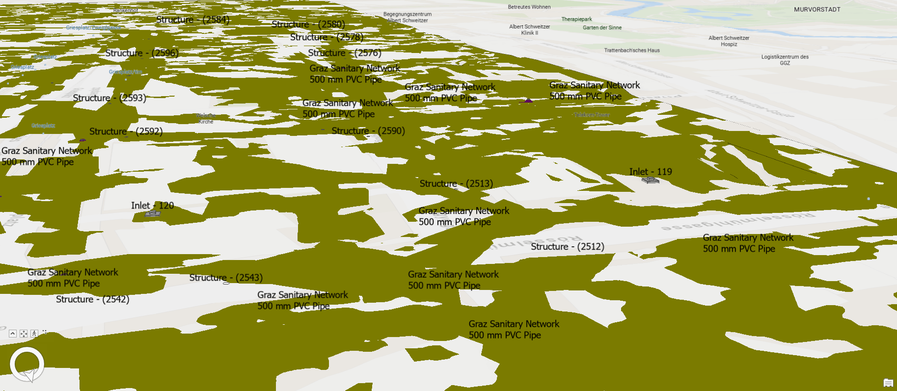
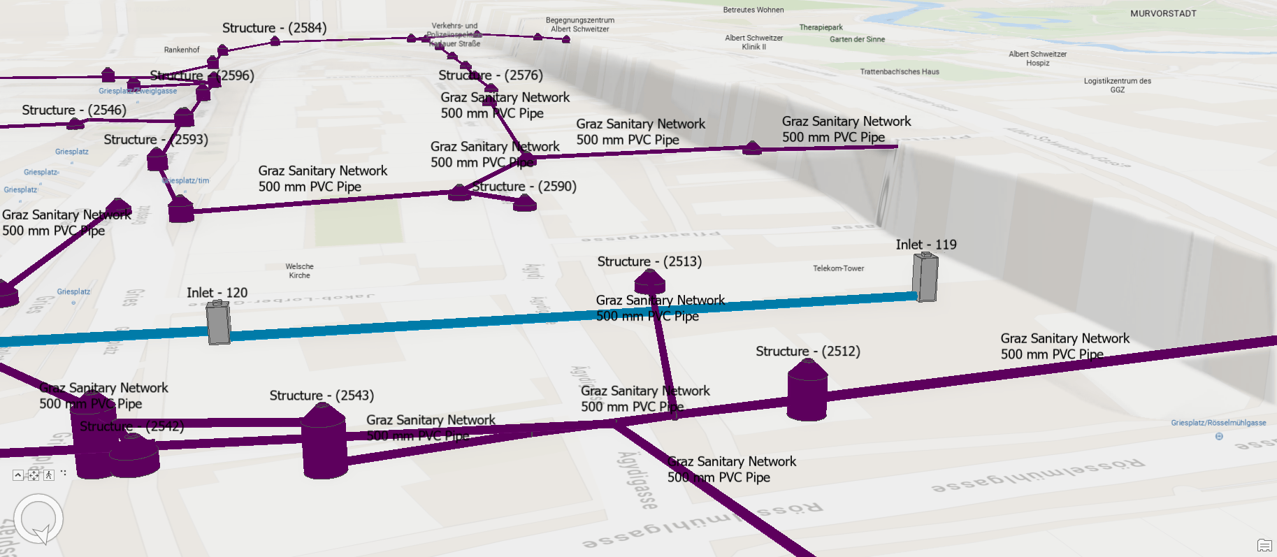
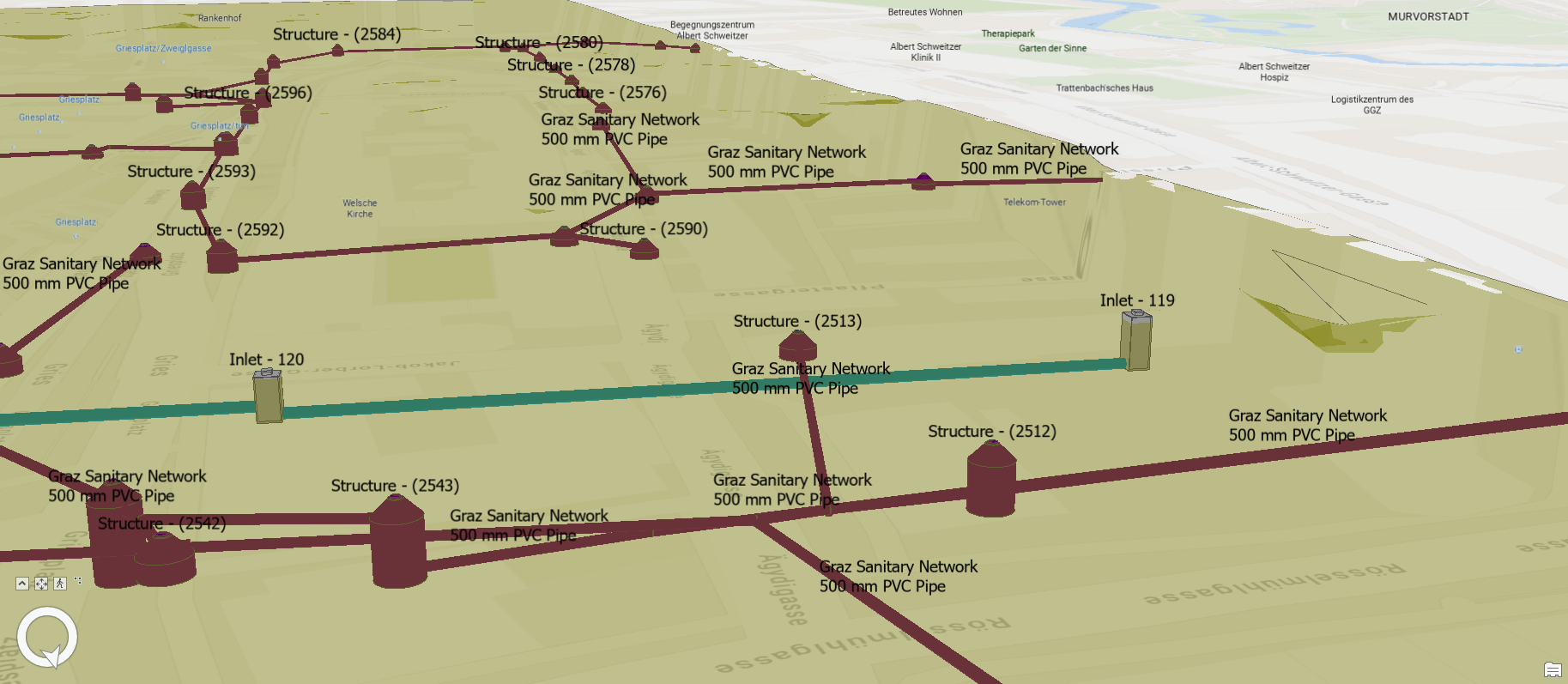
3. To verify that the new raster file is modifying the definition of ground for the scene, temporarily turn off the Topography feature layer (the layer created in the first section).
For example, as shown below, if underground utilities are present in the scene, those elements will become visible.
Increase the transparency of the feature layer representing the proposed surface
As the final step in the workflow, you will Increase the transparency of the feature layer representing the proposed surface.
- Turn back on the Topography feature layer created in the first section.
- Select and right-click the Topography feature layer in the Contents pane.
- Select Symbology to access to the symbology definition.
- Click the layers symbol as highlighted below, expand the Color drop-down menu, and select Color Properties.
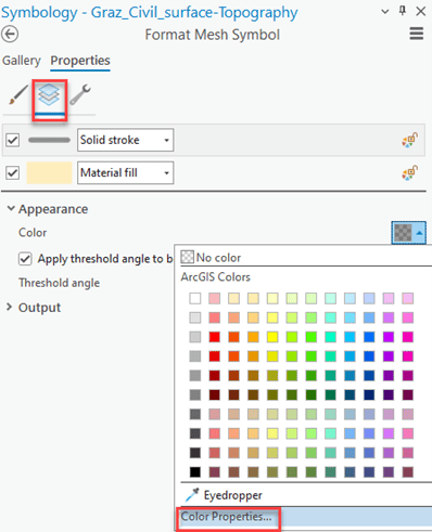
5. In the Color Editor pane, change the Transparency value to the desired level (for example, 60%) and click OK.
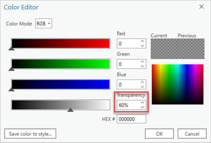
6. Next, click Apply, which saves the changes in the symbology definition and refreshes the scene.
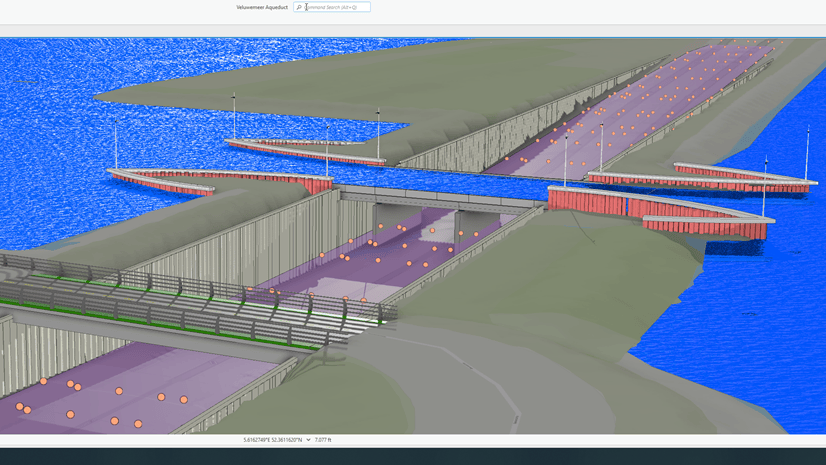
You now have a scene for visualizing the existing ground, the proposed ground (the Topography feature layer with transparency), and any built components that lie beneath the proposed ground.


Article Discussion: