
Introduction
In this walkthrough, you assume the role of a GIS analyst at a small municipality who is tasked with implementing your utility network. You used the Utility Network Migration Wizard to migrate your data to a utility network for a prototype and have discovered that your data contains thousands of topology errors! You know that getting through this process takes time and patience, but you aren’t sure where to start and what tools or resources are available to make this process easier.
This exercise will show you how to use the Migration toolset to identify data quality issues and determine which ones require source data cleanup and which ones are appropriate for automated data cleanup. You will then learn how to perform automated data correction for your topology errors.
The dataset used in this exercise is a utility network dataset that was migrated from a geometric network using the Utility Network Migration Wizard. This means it is a utility network with limited configuration, and a data model that is different from the industry standard models provided by Esri in the Utility Network Foundations.
This exercise was written using ArcGIS Pro 3.5. You can perform most of this exercise using ArcGIS Pro 3.3 as long as you download a standalone copy of the Migration toolset for ArcGIS Pro 3.3. The estimated time to complete this exercise is 30 minutes.
- Analyze network data
- Run the Analyze Network Data tool
- Review results
- Conclusion
- Specify corrections
- Review error summaries
- Resolve missing junctions
- Resolve stacked points
- Resolve snapping issues
- Conclusion
- Apply error resolutions
- Run the apply error resolution tool
- Enable the network topology
- Conclusion

Part 1: Analyze network data
In this part of the exercise, you will learn how to use the Analyze Network Data tool and its output to analyze and review the topology errors associated with your utility network data. This is a fast and easy way to identify any important topological errors that you need to resolve in order to build a fully connected utility network.
Section 1: Run the Analyze Network Data tool
In this section you will run the Analyze Network Data tool to create an analysis database and layer file that describes all the topology errors in your utility network.
1. Download the sample project and open it.
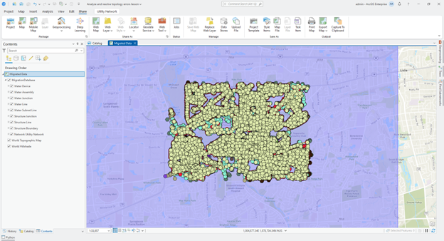
This project includes the sample data and a map you will use for this exercise.
2. Open the Analyze Network Data tool
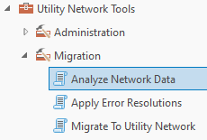
3. Use the dropdown on the Input Utility Network parameter to select the utility network from the current map.
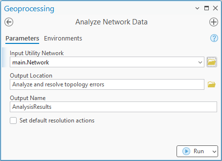
The tool will default the output location and name for you.
4. Click Run
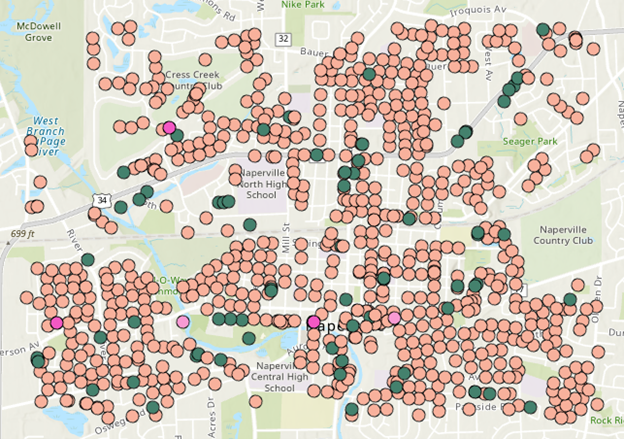
When the tool completes it will add the results of the analysis to your map.
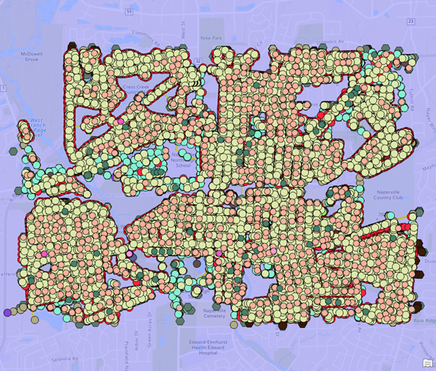
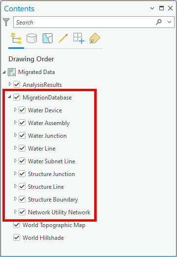
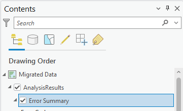
5. Turn off the Migration Database layer in the map
This will make it easier to review the errors in the map for the next section of this exercise.

Section 2: Review results
In this section you will review and learn the purpose of the different outputs created by the Analyze Network Data tool. It is always a good idea to review all the outputs of the tool before you perform any data corrections.
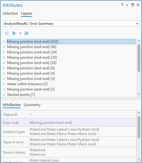
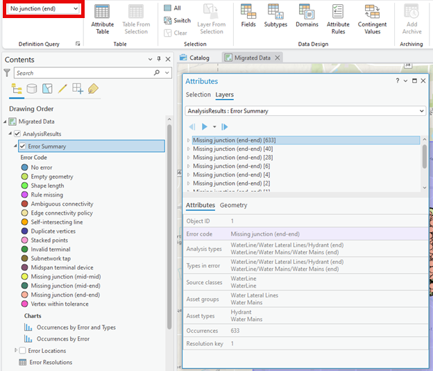
1. Look at the Error Summary layer in the Contents pane.
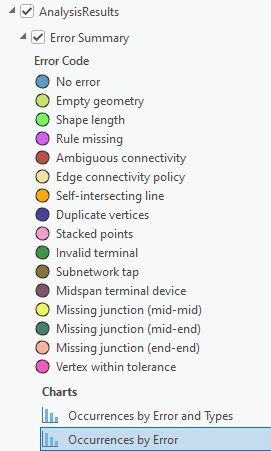
Each error feature on the map is color coded using the type of error it represents.
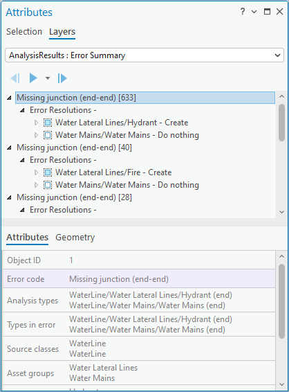
2. Use the Select tool to select one of the missing junction feature errors in the map.
Each error summary represents a collection of features that share a common problem. This is why the geometry type of the layer is a multi-point, allowing one feature to have many geometries.
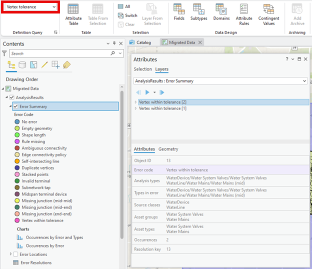
3. Use the Attributes pane to review the attributes of the Error Summary feature.
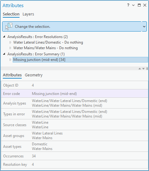
- The Error code field indicates the type of error that was discovered.
- The Analysis types field shows all the feature types that are at the location where the error was found, including features that are coincident but do not have an error.
- The Types in error field shows the types of features that generated the error, in this case a curb stop valve and a distribution network junction.
- The Occurrences field shows how many instances of this type of error are found with these combinations of features.
- The Error Summary feature is a multipoint geometry that contains a point for each location where a combination of features meets these criteria.
4. Turn on the Error Locations layer.
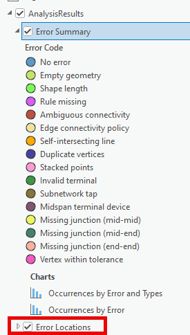
The Error Locations layer represents errors as separate features that is better suited to manual review.
5. Turn on the MigrationDatabase layer in your map.
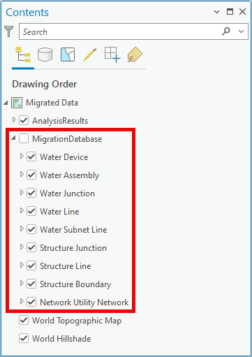
You will want to turn this layer on so you can see features from the migrated data alongside the error features.
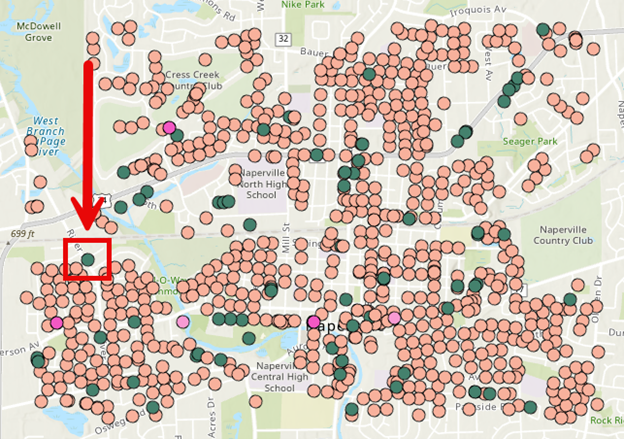
6. Open the Missing Junction bookmark.
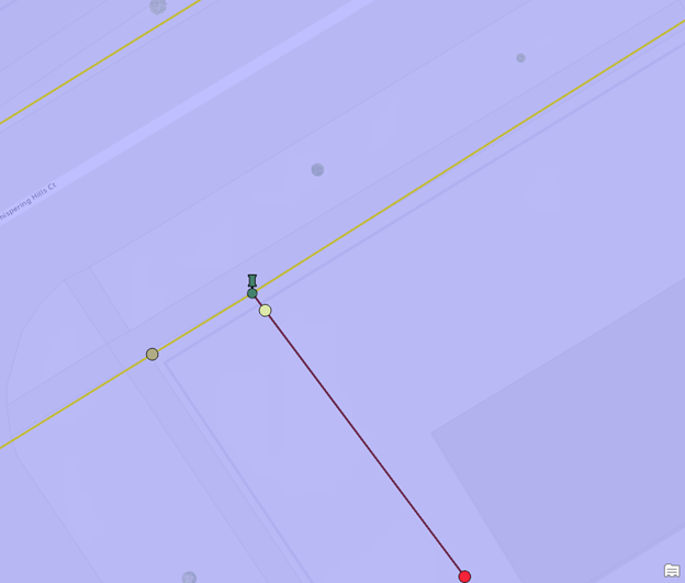
This zooms you to one of the Error Location features for a missing junction.
7. Clear your selection.
8. Select the Error Location feature.
The error location feature looks like a pin.
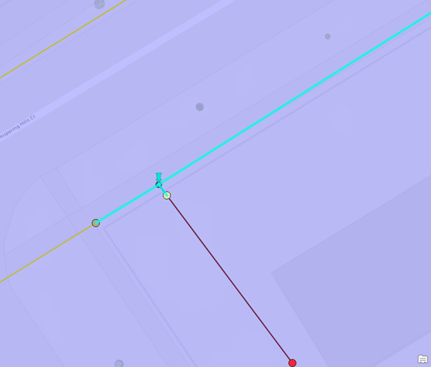
This will select the lines that are responsible for the missing junction error.
9. Clear your selection.
10. Open the Occurrences by Error chart on the Error Summary class.
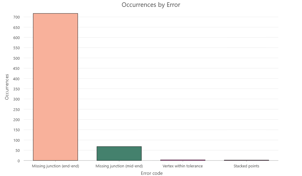
This chart shows the number of instances of each error that was discovered by the analysis.
11. Open the Occurrences by Error and Types chart.

This chart shows how many different combinations of errors and types of features there are.
Part 1 conclusion
Now that you understand the purpose of each of the layers and how they are used to review topology errors in your utility network you are ready to start reviewing all your errors and determining error resolutions.
Part 2: Specify corrections
Each unique combination of errors and types identified by this tool provides an opportunity to resolve a problem with your data. To resolve an error through automation, you must populate one or more actions on the Error Resolution records then run the Apply Error Resolutions tool. If you want to leave an error unresolved so a user can fix it in the source data, or resolve it manually in the utility network, then you can leave the action with the default value of Do Nothing.
In this part of the exercise, you will review each error in the Error Summary layer and populate the actions on their corresponding Error Resolutions. The actions you use to resolve an error may be different, depending on whether you are resolving an error for a prototype or for a production migration. As an example, you may decide to delete stacked point features when creating a prototype of a utility network. For your final, production migration you want to offset the stacked point features or leave them unresolved, so editors have to manually review and correct stacked point features after migration.
All your edits will be to the error analysis layers and database. The migrated utility network data is not modified until the last part of this exercise, when you run the Apply Error Resolutions tool.
Section 1: Review the error summaries
Before you make any edits, you will learn how to use the Layers tab on the attributes pane to review each of the errors. This is one of many ways to review data but is often used when you need to keep track of one set of features you are reviewing while allowing you to freely select and manipulate other features in the map.
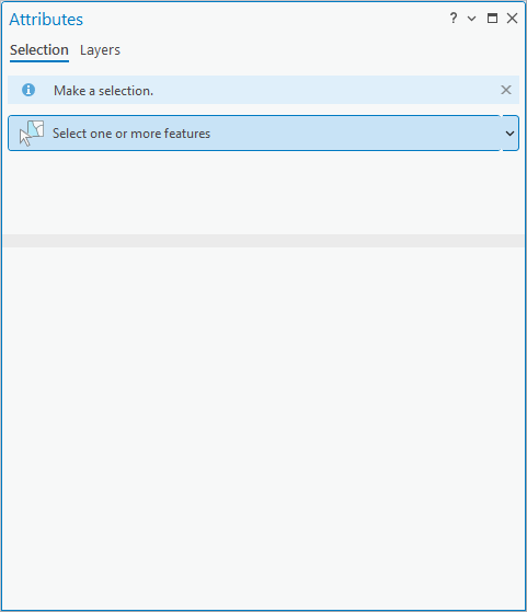
1. Open the Attributes pane.
2. Select the Layers tab.
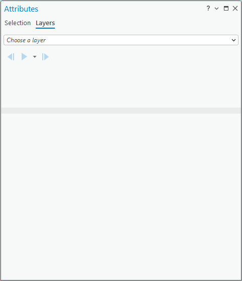
This tab allows you to browse all the records in a layer. The list found under the Layers tab is unique in that it remembers which record you were reviewing even when the current map selection changes.
3. Select the AnalysisResults :: Error Summary layer in the dropdown.
This list includes all the active Error Summary features in the current layer.
4. Select the Error Summary layer in the Contents pane.
5. Select the Data tab on the Ribbon.
6. Look at the active definition query in the Definition Query group
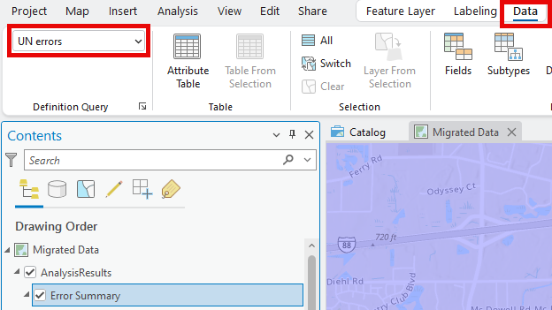
By default, the layer has the UN errors definition query. This filters out quality assurance related issues that do not create topology error or connectivity issues.
7. Click the dropdown for the active definition query in the Definition Query group
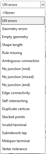
Each of these definition queries corresponds to one or more Error Codes identified by the Analyze Network Data tool.
Section 2: Resolve missing junctions
Missing junction errors are caused when two or more different types of lines are drawn in a way that they could be connected, but there isn’t a device or junction that allows them to be connected. The most common resolution to this is to create a junction that allows the features to connect.
1. Select the Error Summary layer in the Contents pane.
2. Select the Data tab on the Ribbon.
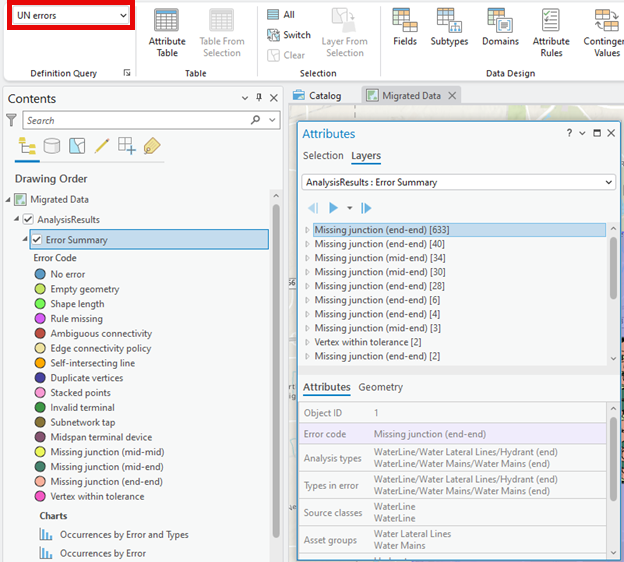
3. In the Definition Query group, set the definition query for the layer to No junction (end).
These are situations where the endpoints of multiple lines are connected without a junction feature.
4. Select the first Missing junction Error Summary record.
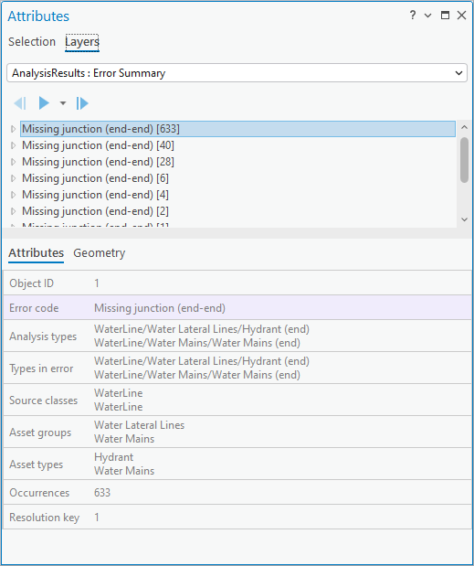
You can see that there were 633 occurrences where a Hydrant Lateral line is snapped to a Water Main without any kind of fitting.
5. Expand the first Error Summary feature so you can see its associated Error Resolutions.
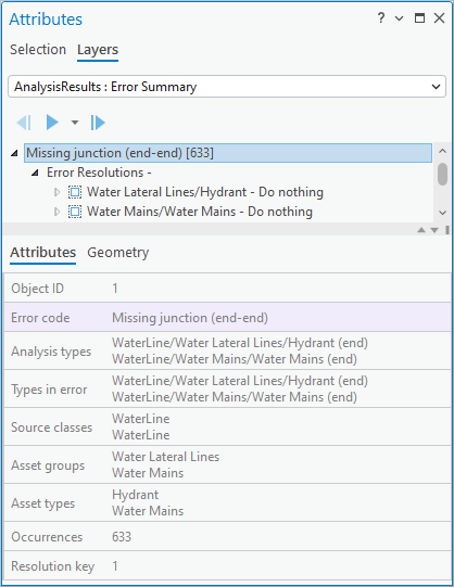
Each Error Resolution allows you to apply a corrective action to the feature. Depending on the situation you may specify an action for one, or all the records. You can see that there are no actions associated with these features because their display expression says Do nothing.
6. Select the Error Resolution for the Water Lateral Lines/Hydrant
7. Populate its attributes with the following values
- Set the Action to Create.
- Set the Create/Update type to WaterJunction/Water Fittings/Tee.
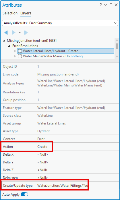
If you don’t have Auto-Apply enabled, click Apply to apply your edits.
8. Repeat this resolution for the remaining Missing Junction (end-end) errors.
- If there is a lateral connected to a main, create the Tee on the lateral.
- If there are multiple laterals, only create a Tee on the first lateral.
- If you create multiple point features on the same error, this will result in new stacked point feature errors.
9. In the Definition Query group, set the definition query for the Error Summary layer to No junction (mixed).
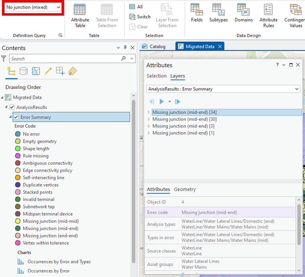
These summaries represent features where the endpoint of one line connects midspan on another line without a junction or device.
10. Apply the same logic you used to resolve the Missing junction (end-end) errors to these errors.
11. Save your edits.
12. In the Definition Query group, set the definition query for the Error Summary layer back to UN Errors to see all the errors.
In this section you reviewed all the Missing junctions that will cause topology errors. You did not review or provide resolutions for any No junction (mid) features because these features are included for informational purposes only.
A No junction (mid) feature is created whenever two lines share a common vertex midspan on each line. The utility network will not establish connectivity between these features, nor will it create a topology error. In some cases, you may want to review these locations to ensure that the features should not be connected, or you may even have a cartographic standard that doesn’t allow for this.
You can find examples of the different resolutions for this issue in the Resolving topology errors article.
Section 3: Resolve stacked points
Next you will review all the areas where stacked point features were discovered. These are situations where two or more devices or junctions, that don’t belong to a structure network, occupy the same location.
1. Select the Data tab on the Ribbon.
2. In the Definition Query group, set the definition query for the layer to Stacked points.
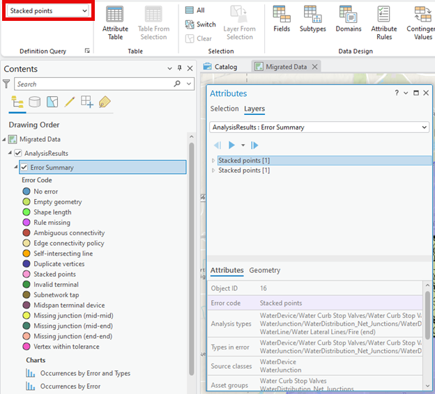
3. Go to the Layers tab on the Attributes pane.
4. Select the first Stacked points error.
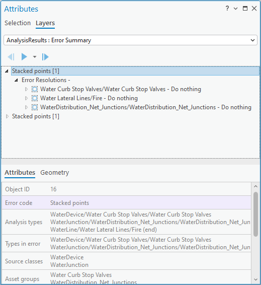
In this instance, a curb stop valve is stacked (coincident) with a water distribution network junction.
5. Select the Error Resolution for the WaterDistribution_Net_Junctions.
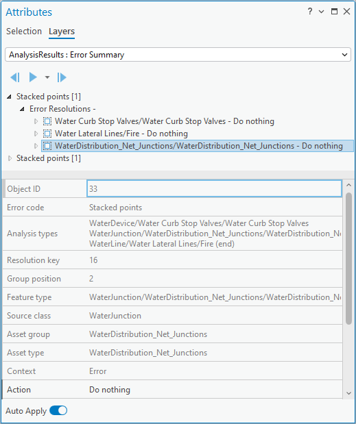
6. Set the Action to Delete All.
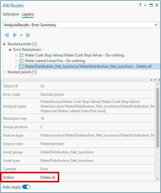
This action will delete the network junction while keeping the curb stop valve.
7. Repeat these steps for the second Stacked points error
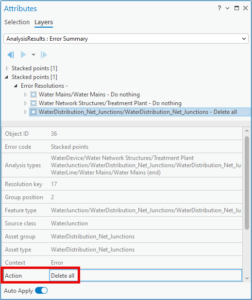
8. Save your edits.
9. Select the Data tab on the Ribbon.
10. In the Definition Query group, set the definition query for the layer to UN Errors to see all the errors.
In this section you reviewed all the Stacked point features. For each scenario, you ensured that only one feature was left in place by deleting the other feature. Another common resolution to this problem is to use the Update All or Update all but first action along with a Delta X/Y/Z/step to offset the features. You can find examples of the different resolutions for this issue in the Resolving topology errors article.
Section 4: Resolve snapping issues
Next you will be reviewing Vertex within tolerance features. These are situations where multiple features are extremely close to each other but are not close enough that they can be consistently connected. These features will not create topology errors, but if they aren’t resolved then these features can end up being disconnected when you attempt to trace them, even if they don’t create a topology.
To resolve these issues, you will set one feature to act as an anchor, and the other nearby features to snap to that feature.
1. Select the Data tab on the Ribbon.
2. In the Definition Query group, set the definition query for the layer to Vertex Tolerance.
This will show all the locations where two or more features are very close to each other but not snapped.
3. Go to the Layers tab on the Attributes pane.
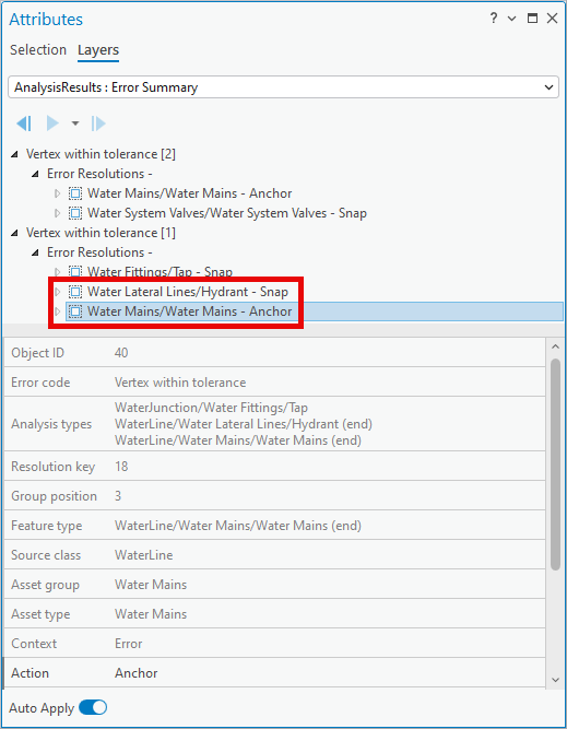
4. Select and expand the first Vertex within tolerance error.
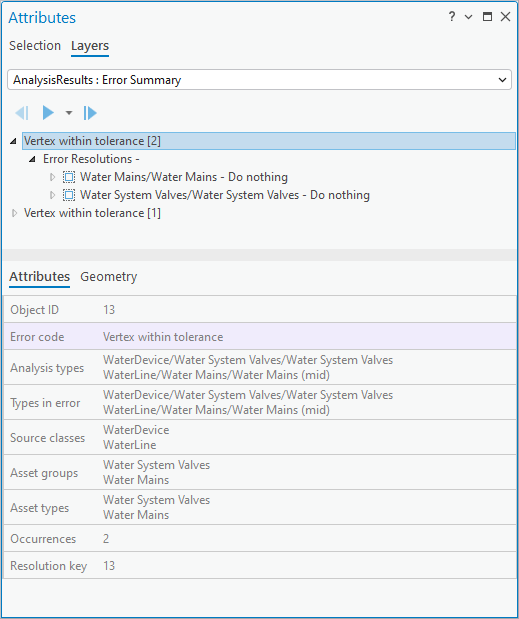
This error represents two locations where system valves aren’t properly snapped to nearby water mains.
5. Select the Error Resolution for the Water Main.
6. Set the Action to Anchor.
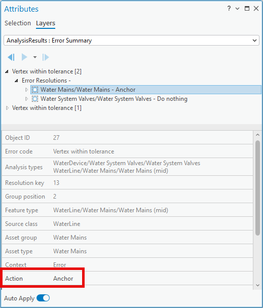
This will ensure the geometry of the water main will not be affected by the error resolution.
7. Select the Error Resolution for the Water System Valve.
8. Set the Action to be Snap.
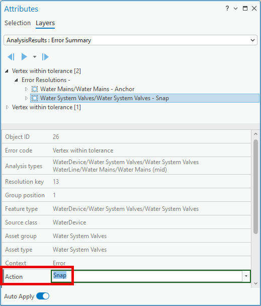
This will snap the Water System Valve to the vertex on the nearby Water Main.
9. Repeat this process for the second Vertex within tolerance error.
This resolution will keep the vertices of the water main in the same location and snap the endpoint of the lateral and the water fitting to that vertex.
10. Save your edits.
11. Select the Data tab on the Ribbon.
12. In the Definition Query group, set the definition query for the layer to UN Errors to see all the errors.
In this section you reviewed all the Vertex tolerance features that can cause connectivity issues. For each scenario you ensured that all the features would be snapped to a single anchor feature. In these examples you chose to snap any junctions or devices to lines, but depending on your organizations standards you could also have chosen to use a particular junction or device feature as the anchor location. You can find examples of the different resolutions for this issue in the Resolving topology errors article.
Part 2 conclusion
Now that you’ve specified at least one action for each Error Summary, you have defined a plan that can be used to correct problems with your data. The actions you defined in the Error Resolutions table will be applied using the Apply Error Resolutions tool which is discussed in the next part of the exercise.
Part 3: Apply error resolutions
In this part of the exercise, you will apply the error resolutions you defined previously to the migrated data. This step is important as it allows you to verify that the planned actions you defined earlier successfully resolve all the errors in the network.
Because you defined actions for all your problems you can use the Enable Network Topology tool to build your topology and confirm this. If you decided to leave some issues for manual cleanup you could either run Analyze Network Data a second time to confirm the expected issues remain, or you could enable the network topology and be prepared to manually resolve the resulting topology errors.
Section 1: Run apply error resolution tool
Up to this point you have used the results of the Analyze Network Data tool to provide instructions for how you would like to resolve them. In this section you will use the Apply Error Resolutions tool to perform the actions specified on each Error Resolution to the corresponding features in your utility network.
1. Open the Apply Error Resolutions tool.
2. Populate it with the following parameters.
- For the Input Utility Network select the utility network from the database included in the project
- For the Resolution Table select the Error Resolutions table from the map
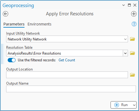
You do not need to populate the Output Location or Output Name fields to run the tool. These additional optional parameters cause the tool to generate an edit log that records all the edits made to the layers in the utility network.
If you only want to apply some of your error resolutions, you can select the corresponding records when you run this tool. In that case the Use filtered records message indicator will be replaced with an indicator to Use the selected records.
3. Click Run.
Once the tool completes you are ready to verify the tool fixed all the issues in your data that could result in topology errors.
Section 2: Enable the network topology
After you have applied your error resolutions, you can verify that you have a valid topology by enabling the network topology.
1. Open the Enable Network Topology (Utility Network) tool.
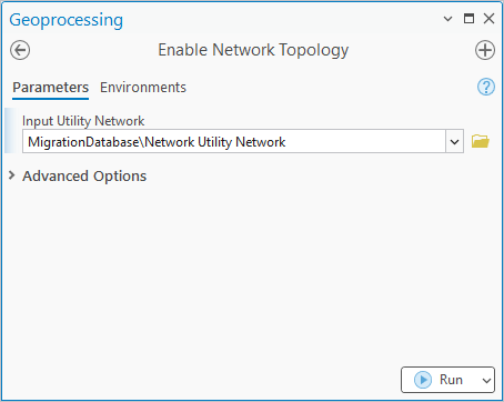
Use the utility network from the current map as the Input Utility Network.
2. Click Run.
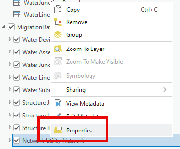
3. Select the Network Utility Network layer in the map.
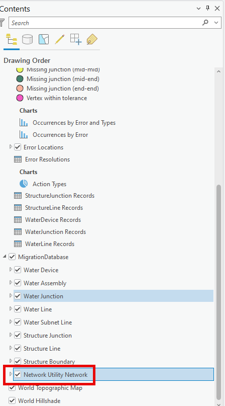
4. Right click the layer and select Properties to open the Layer Properties dialog.
5. Select the Network Properties page in the Layer Properties dialog.
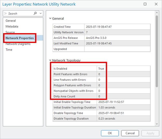
This page allows you to verify that the network topology is enabled and there are no topology errors or dirty areas.
Lesson conclusion
In this exercise you learned how to run the Analyze Network Data tool to identify topology issues in your utility network. You then saw how this tool outputs a database that describes all the topology issues that were identified in your network.
You reviewed each Error Summary and ensured an appropriate action was taken on the corresponding error features. This created a series of instructions that were used by the Apply Error Resolutions tool to correct all the topology issues.
Finally, you were able to confirm that the actions you defined were all appropriate resolutions by enabling the network topology and confirming that the resulting topology is error-free.
Check out some of the additional resources below:
- If you want to learn how the data for this tutorial was migrated, check out the Utility network migration wizard walk through.
- This walk through was based on the articles written for Analyzing Topology Errors and Resolving topology errors.
- To learn more about utility network data migration, check out the ArcGIS Utility Network migration reading list.
- For industry-specific resources on the utility network, check out the Getting started with the utility network learning series.


Commenting is not enabled for this article.