
Introduction
Update 11/14/2025: You can now find the Try the Utility Network Migration Wizard tutorial in the Documentation Gallery that covers this content. Going forward refer to that tutorial, since it will be updated to reflect the latest tools and best practices with each network management release.
In this walkthrough, you assume the role of a GIS analyst at a small municipal government tasked with a pilot project to migrate your organization’s data to a utility network. Your small city has departments that manage data for electric, gas, water, wastewater, and stormwater. This exercise includes sample data and instructions for migrating each of these five datasets, so you can focus on using the dataset you are most comfortable with. You will learn to use the Utility Network Migration Wizard to create a new utility network using your existing geometric network.
You understand that the utility network created by this tool doesn’t include configurations to perform advanced capabilities. Still, because you are focused on data quality issues and familiarizing yourself with the basic concepts of the utility network, you have decided this is the best approach. You know that once you’ve finished your initial migration, you can use the Analyze Network Data tool to identify all the topological errors in your database.
In order to complete this exercise, you will need ArcGIS Pro 3.5. The estimated length of the exercise is 15 minutes.
You can use the links below to navigate between the different sections of the exercise:
- Initial Setup
- Identify a service territory
- Open the migration wizard
- Part 1 conclusion
- Map Source Data
- Utility network mappings
- Finish the wizard
- Conclusion

Part 1: Initial Setup
In the first part of this lesson, you will learn how to run the Utility Network Migration Wizard and what steps you can take to ensure the entire data migration process goes smoothly.
Section 1: Identify a service territory
Every utility network requires a Service Territory to define the extent of the utility data that it manages. Before you begin your data migration, ensure you have a polygon feature class that fully covers your current and future assets in the same spatial reference as the rest of your network data.
1. Download the sample project and open it. The project includes sample geometric networks and maps for the following utilities:
- Electric
- Gas
- Sewer
- Stormwater
- Water
2. On the Catalog pane expand Folders. Expand the Project folder. Expand commondata. Expand the Utilities database that you are most interested in.
 |
 |
 |
 |
 |
|
The utilities database in your project should contain a ServiceTerritory polygon feature class.
Each utility network requires a Service Territory polygon to define the extent of the data to be managed in the utility network. Make sure you select or create a layer that completely covers your current and future service territory because the extent cannot be expanded once you’ve created your utility network.

Section 2: Open the migration wizard
In this section you will run the Utility Network Migration Wizard to migrate your data to a utility network.
1. In the Catalog pane, expand Folders. Expand the project folder. Expand the commondata folder. Expand the utilities database. Expand the feature dataset. Select the geometric network according to the image below.
 |
 |
 |
 |
 |
|
2. Right click the geometric network and select To Utility Network… to launch the Utility Network Migration Wizard

3. Take a moment to read the instructions on the first page of the wizard before clicking Next

4. Click Next
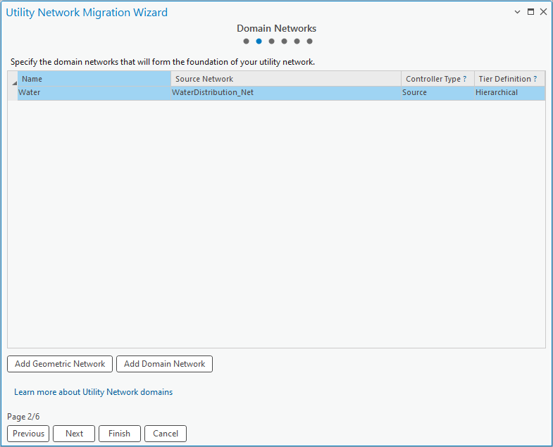
Set the values for the Name, Source Type, and Tier Definition columns using the image below.
 |
 |
 |
 |
 |
|
This first row was populated with the geometric network you selected. You can add additional geometric networks using the Add Geometric Network button. If you launched the tool without a geometric network, use Add Domain Network button to add a domain network for the classes you want to migrate.
5. Click Next
6. Populate the first page of the wizard with the following parameters:
For Service Territory Polygon, browse to the choose the Service Territory feature class.
For Output Folder, choose the project folder

If your network features have attachments or other relationships you want to migrate, select those options. Accept the defaults for the rest of the parameters at this time.
7. Click Next
8. The next page shows all the feature classes from the geometric network that you can migrate to the utility network. You will adjust the mappings in the next module.
 |
 |
 |
 |
 |
|
Part 1 conclusion
You have learned how to prepare your data to be migrated to a utility network and how to launch the Utility Network Migration Wizard on geometric network datasets. You have also learned that you do not need a geometric network to use this wizard.
You can learn more about the parameters of this tool by reading the Use the wizard to migrate data into a utility network section in ArcGIS Help.
Part 2: Map source data
In the second part of this lesson, you will finish mapping your source classes to features in a new utility network and run the migration.
Section 1: Utility Network Mappings
In this section you will update the mappings for all the classes in your geometric network to ensure they are migrated into the new utility network the way you want them.
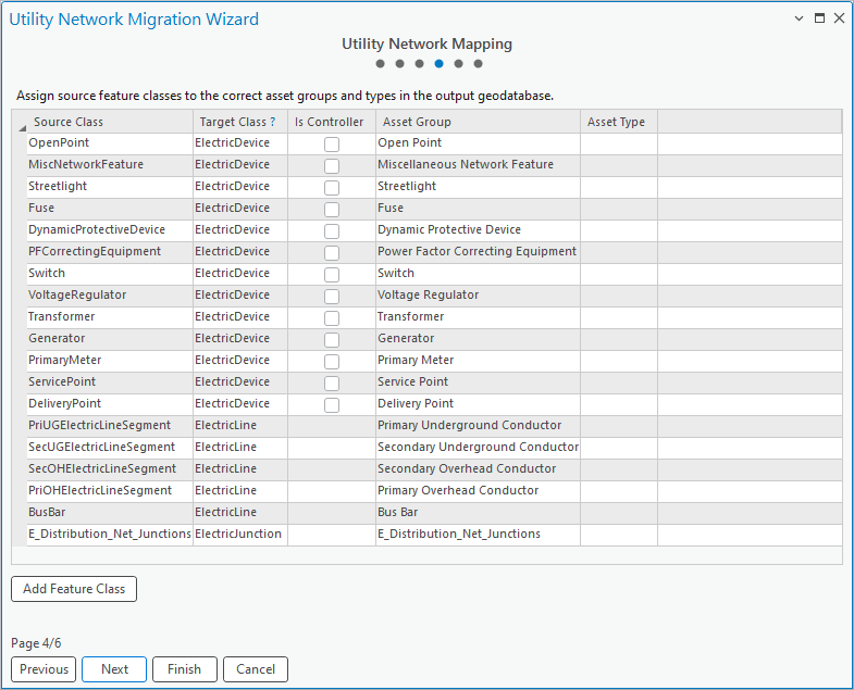
1. Review the Source Class column to ensure all the classes you want to be migrated to your utility network are present
When classes are imported from a geometric network, the Target Class is selected automatically based on the geometry type of the layer. You can adjust the target class to a different domain class or structure class, depending on your model. Additional classes can be added using the Add Feature Class button.
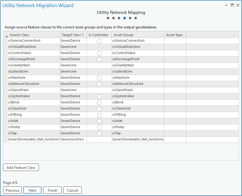
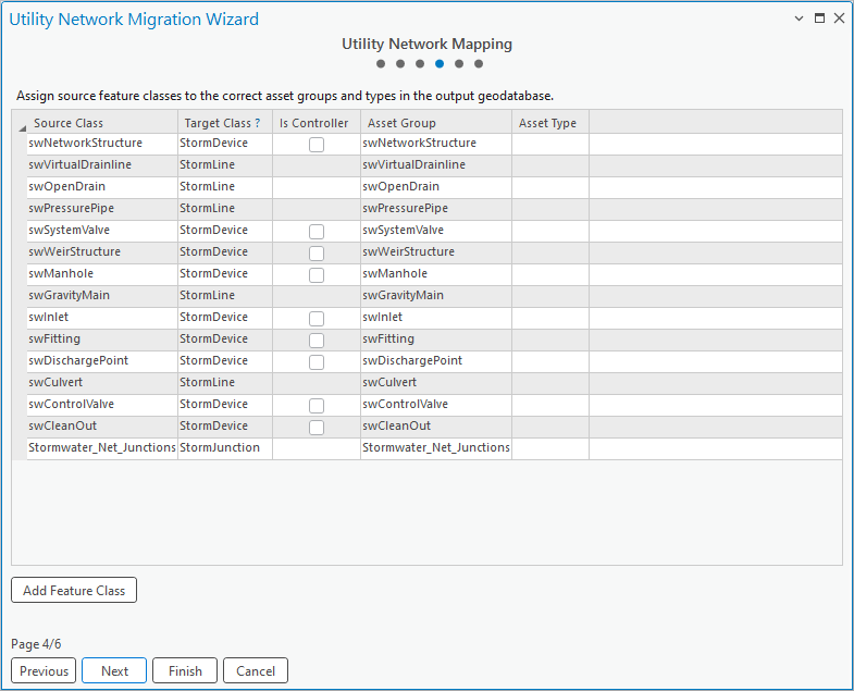
2. Check the Is Controller box for any sources/sinks in your network. Refer to the graphics below for suggestions:
 |
 |
 |
 |
 |
|
A layer that is configured as a controller contains the features that act as the ultimate sources/sinks in the network. Selecting this option will configure asset types in that asset group in the network to be capable of acting as subnetwork controllers.
If you aren’t certain which layers to use, leave the column blank. You can configure sources/sinks after you migrate your data and are more familiar with the utility network.
3. Set the values in the Asset Type column for the following classes to match the screenshots below
 |
 |
 |
 |
 |
|
Populating the Utility Network Mappings page is the most time-consuming and thought-intensive part of the entire migration process. Now that you’ve completed mappings, you are only a few steps away from finishing the migration!
Section 2: Finish the wizard
In this section you will review a summary of the configurations for the migration and review the output.
1. Click Next
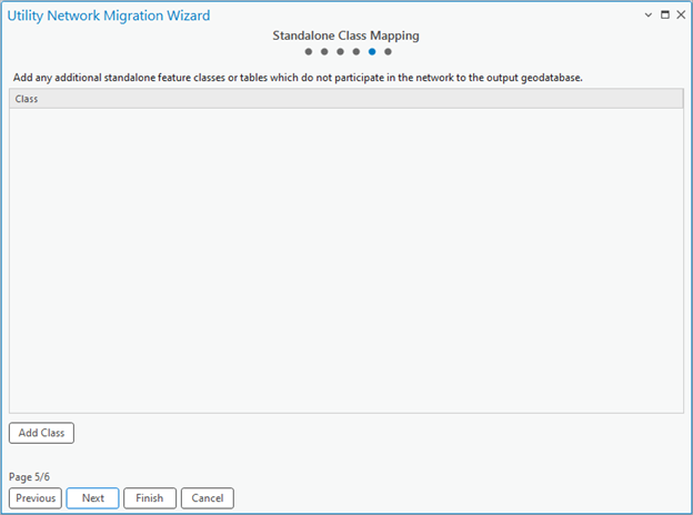
If you had additional tables or feature classes you wanted to include in your new database, you would add them using the Add Class button on this page.
2. Click Next
The summary page allows you to review your configuration before running the migration. Use the Previous button to go back to the corresponding page and make any changes.
3. Click Finish to run the migration.

This will run the Migrate To Utility Network tool with the configuration you specified in the wizard. The tool takes several minutes to create a new utility network and migrate your data. It will take longer on larger datasets. If you have a map open when the tool finishes running, it will add layers for the new utility network to your active map.
4. In the Catalog pane refresh the project folder. Expand the MigrationDatabase folder. Right Click the MigrationDatabase.lyrx file and select Add To New Map …

This will create a new map that contains subtype group layers for the contents of your new utility network in it with a default set of symbology.

You are now looking at a new utility network that matches the tables, fields, and domains of the classes from the source geometric network.
5. Refresh the project directory on the Catalog pane to see the MigrationDatabase folder created by the tool.
6. Expand the MigrationDatabase folder.

This folder contains the geodatabase, layer file, and other outputs created by the tool.
6. Open the History pane by going to the Analysis tab on the Ribbon and clicking History.

You can see that the wizard ran the Migrate To Utility Network tool. If you want to make changes to your migration, you can right-click this and open the tool with all the settings from your initial run.
Lesson conclusion
Now that you have migrated your data to a utility network, you can begin exploring your data in a utility network. If your data has topology errors, which is likely, you will be unable to perform any tracing or analysis using your utility network until you analyze and resolve these issues. If you want to know more about how to fix topology errors, read the Analyzing topology errors and Resolving topology errors articles. If you want to try these tools on a sample dataset, check out the analyzing and resolving topology errors tutorial.
Once you have an error free and enabled network topology you can be confident that you can perform tracing, although you will still need to perform quality assurance to ensure that the network attributes and connectivity in your network produces valid results.
Additional Resources
If you want to know more about utility network data migration, check out the ArcGIS Utility Network migration reading list.
If you’re looking for more resources to learn about the utility network, check out the Getting started with the utility network learning series.


Commenting is not enabled for this article.