Ready to generate a network diagram? Today, we are going to show you how to make a simple network diagram by selecting features in the map. Creating a diagram is not a difficult process. We will cover the basics of creating and using network diagrams, with a focus on beginner tips and tricks. By the end of this post, you will be ready to start diagramming your networks.
What are network diagrams exactly?
A network diagram is a simplified view of your assets and how they are connected. This is often referred to as a schematic. I like to think of everything in the map as the geographic representation and everything in the diagram as the schematic view. I am using schematics here to teach you how to diagram a proof of concept, reproduce a CAD drawing, or just to see how things are connected.
Network Diagrams are the perfect way to show your system’s connectivity, and they work well for many reasons. For example, let’s say you work at Rail Company X and wanted to see a schematic view of your rail system with from-to measures on the diagram. Or your organization has some old CAD drawings it wants to reproduce using schematics. Network diagrams is the perfect tool in both of these cases. Another reason these visuals might come into play? You have created schematics using the old ArcGIS Schematics extension that need to be updated; on top of creating new ones.
Now you have a basic idea of what network diagrams are and when to use them. Let’s get started. You’ll learn about:
- Generating network diagrams
- Applying layouts
- Storing diagrams
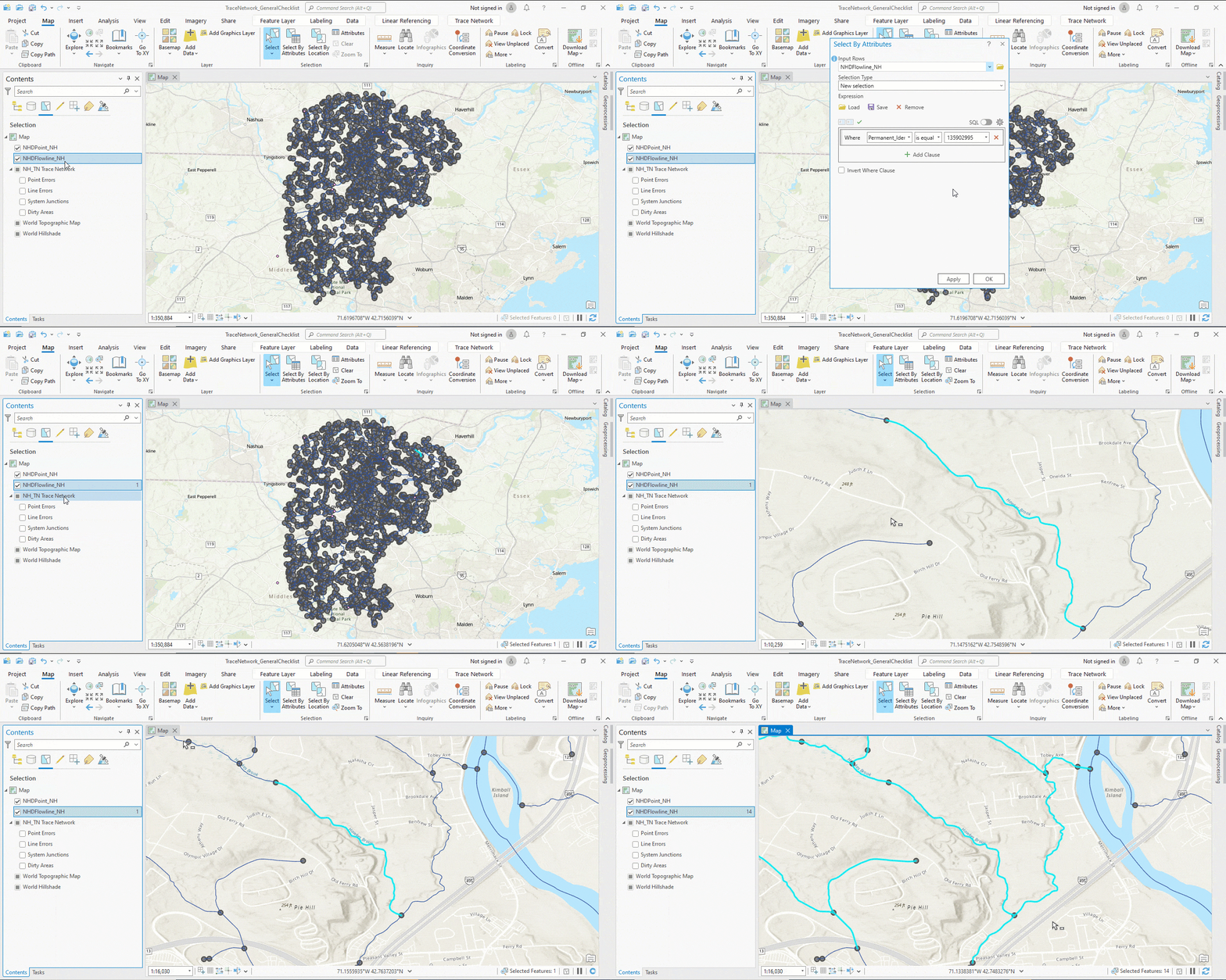
Let’s begin by selecting features we would like to see in the diagram. There are a number of ways to identify features for diagramming—for example, performing a subnetwork trace. Here we will zoom to an area and select the features we want to display.
Tip: I am using a trace network, but this can also be done with utility network features.

Create Diagram
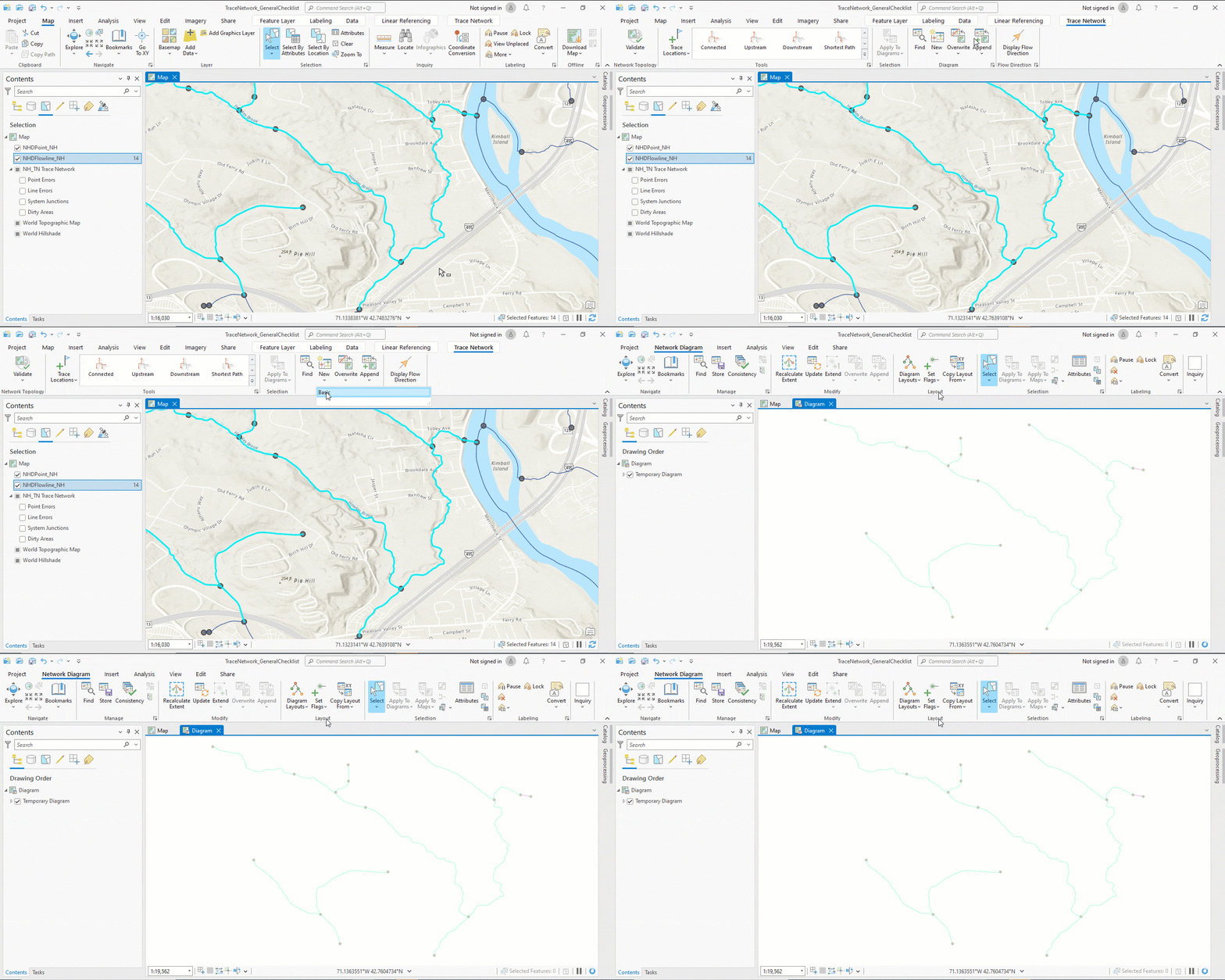
Next, we will want to go to the Trace Network tab and create a new basic diagram. This creates a temporary diagram with all the network features. This is important because you must store a network diagram for it to persist or be saved.

Change Layout
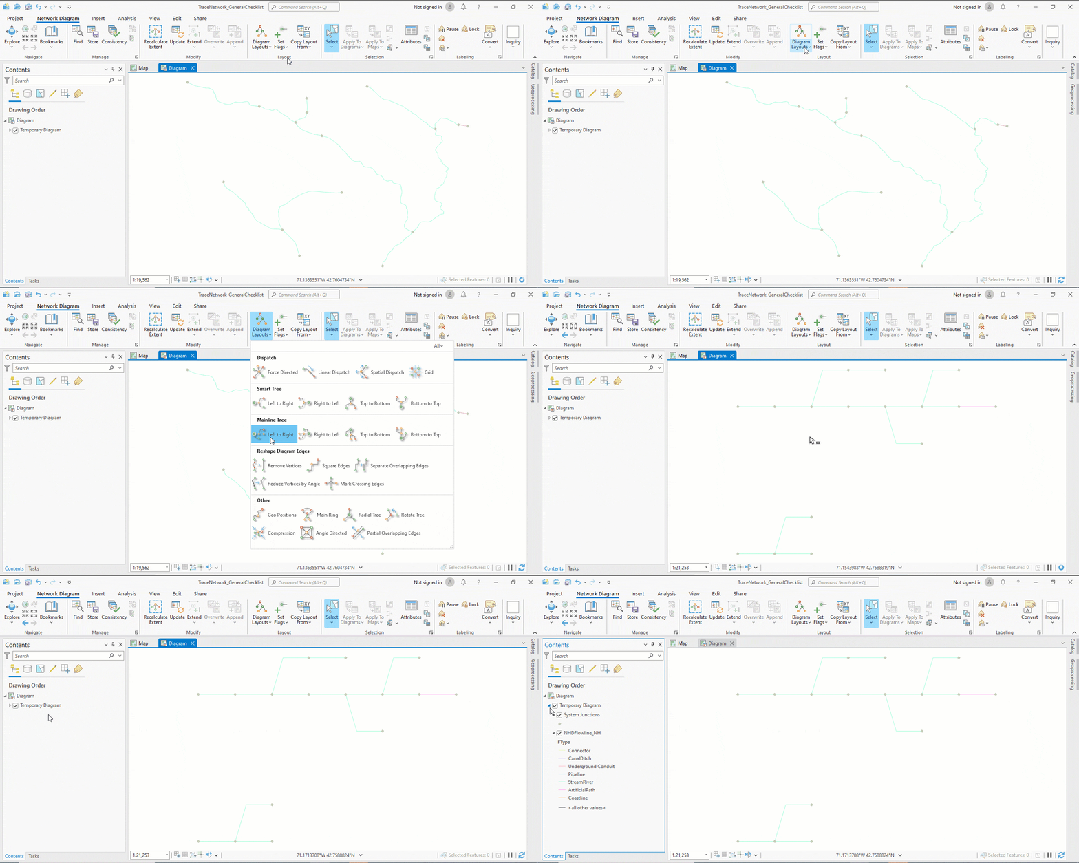
Now we can apply a layout. There are several default layouts. I like to test with a mainline tree diagram layout.
Tip: Diagram layouts are placement instructions used to clear or reduce the spacing between diagram features and make them easier to understand.

Save Diagram
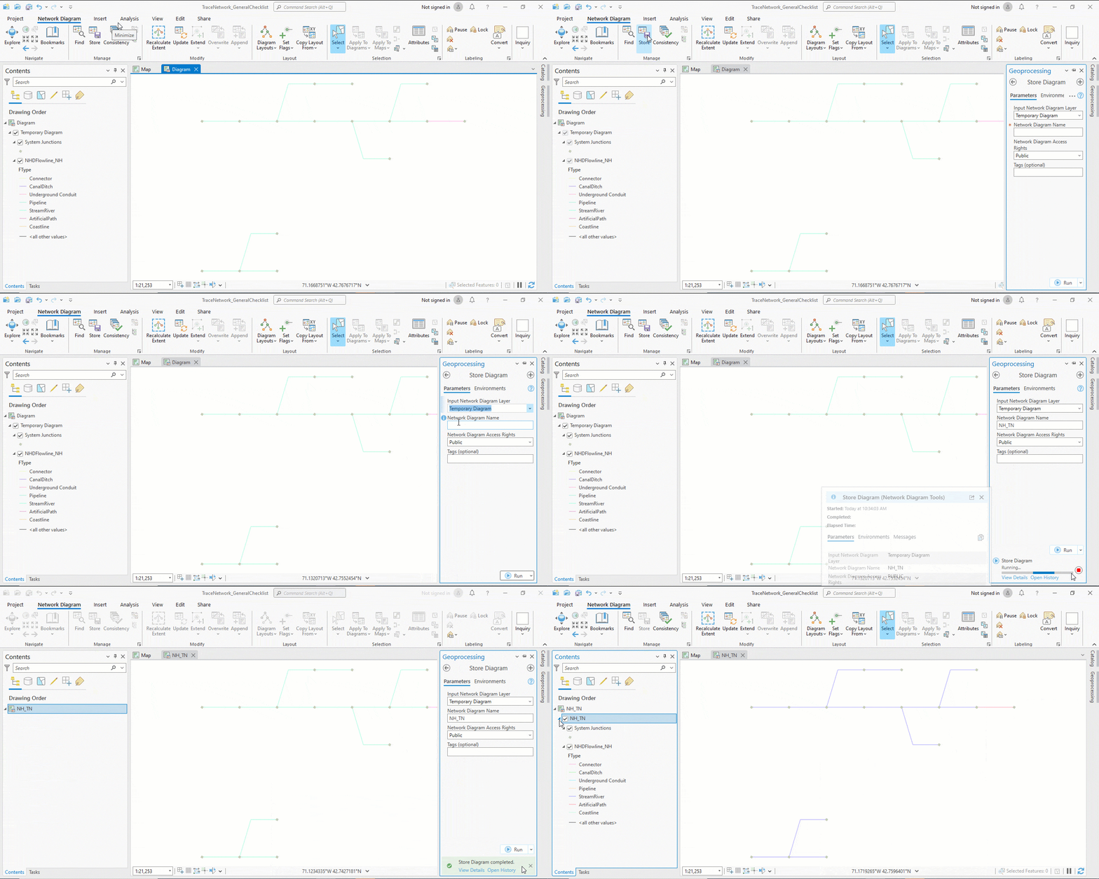
Next, if you want to keep this diagram to open later or share it with others, you can store the diagram.

Why this workflow?
This workflow is good for simplified diagrams such as a switching diagram, which is a schematic diagram of switches that shows their connected features and helps people understand the operation of the switch. But if you want more out of your diagram—like an upstream/downstream diagram starting from a subnetwork control, or a diagram that only shows the transmission part of the network—this will not be enough. You will have to create and configure your diagram templates. Learn more about diagram template configuration.
Let’s Wrap up
At this point, you have everything to make your diagram in four simple steps: select, create, change, and save. Using network diagrams is the only way of going from a geographic representation to a schematic view, it’s entirely seamless!
What layout will you apply? Take time getting acquainted with layouts because it will pay off when you need to edit your network diagram. Lastly, connect on Esri Community.
Article Discussion: