When you generate a network diagram, you choose a diagram template on which to base your diagram. A diagram template contains configuration settings that define how the generated network diagram contents will be built. Keep in mind the following best practices to create great diagram templates!
Start with a diagram template geoprocessing model
Use ModelBuilder and geoprocessing tools and models to configure your diagram templates. The process of building a geoprocessing model iterates through tools in much the same way as the network diagram building process. Models provide better control over the template configuration and enable you to visually ensure the right position and order of each diagram rule and diagram layout in the template rule and layout lists.
To get started with creation of a new diagram template, take a look at the recommended workflow below:
- In ArcGIS Pro, open the Geoprocessing pane and run the Add Diagram Template tool to create the initial diagram template.
- Next, open ModelBuilder. Starting with a blank geoprocessing model, you will use this to chain all the tools and configure the sequence of rules and layouts you want to run to build the network diagram contents.
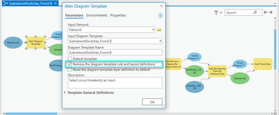
- Add the Alter Diagram Template tool to the model to configure your template basic settings and check the Remove the diagram template rule and layout definitions check box.
This is essential in a diagram template geoprocessing model to ensure that the template rule and layout lists are purged before re initializing all the template settings each time the model is run. Without this option enabled, each rule and layout chained in the model will be added at the end of the template rule and layout lists, causing the same set of rules and layouts to be configured several times, making the content of diagrams based on the template unsuitable.
Consider your diagram template general settings
Depending on the purpose of your template, you should review some of the general settings that are exposed through the Alter Diagram Template tool. Specifically, you should consider the following:
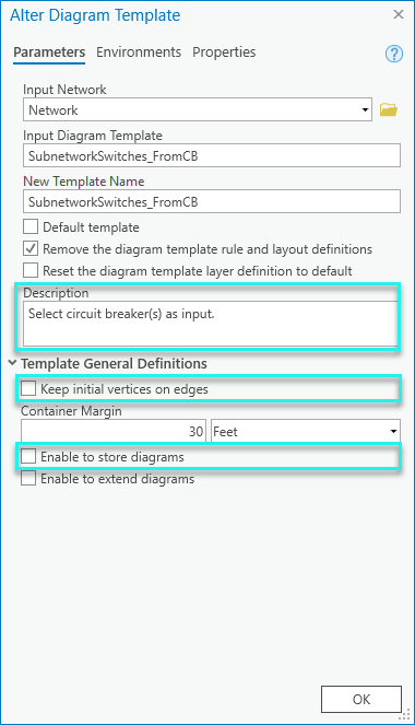
- Template description–Provide information in the Description text box to aid understanding into how your diagram template works and what input network features are expected for diagram generation. This description text will appear for the template in the Diagram Templates section on the Network Properties tab in the network layer properties dialog box.
- Vertices along diagram edges–Copying network line geometries into the diagram edges and managing vertices during the diagram build process is time consuming. To avoid vainly decrease performance, check the Keep initial vertices on edges check box only when necessary. For example, if your template is configured to apply an automatic layout at generation, this is helpful when using the Relative Mainline or Partial Overlapping Edges layouts. Other diagram layout types don’t use vertices on diagram edges when running and would not benefit from this option.
- Diagram storage–To avoid unnecessarily increasing the database size, diagrams should only be stored when necessary. Diagram storage can be blocked at the diagram template level for diagrams that are not relevant; for example, diagram template configured to produce diagrams for network exploration or network data QA. For these types of diagrams, leave the Enable diagram storage check box empty to prevent storage by users.
Diagram template rule and layout definitions
Keep in mind the following fundamentals when configuring rule and layout definitions in your diagram templates :
- Diagram templates are designed to produce a type of diagrams; not to produce a unique diagram.
- These are often configured to focus on a particular type of input network features from which diagram rules are set up to process. For example, diagrams that focus on specific network levels or domains; transmission vs distributions, stations, etc.
- Templates should be set up to provide additional value to the basic diagram template; for example, templates are often configured to display simplified and logical representations of the network using the Reduce Junction and Collapse Containers rules.
- As a diagram template designer, you should strongly consider the use of Trace, Spatial Query, and Expand Container diagram rules when configuring your templates so that resulting diagrams always reflect the true state of network after update. For example, configuring a Trace rule on a diagram template that systematically stops when particular device status values are encountered allows the trace result to automatically reflect the state of the network in the diagrams after its update and following any changes in device status.
- Consider automating the layout of the resulting diagrams to clarify relationships and normalize spacing between diagram features.
Additionally, when chaining the diagram rule sequence that define your template, don’t lose sight of performances at diagram generation and update:
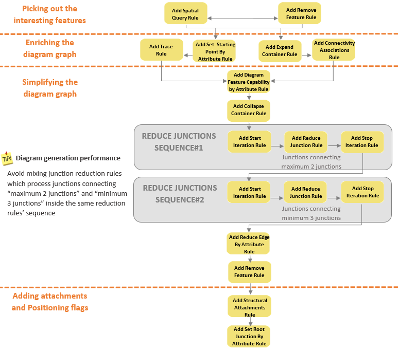
- Use the Remove Feature rule at the beginning of the rule sequence to systematically discard unexpected features. This enables you to focus on the network features of interest when generating diagrams and improves performance with diagram update operations. You can also consider the usage of Remove Feature rules to remove container relations and so simplify the diagram graph.
- Think about configuring Set Starting Point rules when using a Trace rule to clearly identify specific features or junction terminals as starting points from which the Trace rule will run. This also prevents unnecessary trace processes to perform.
- Avoid configuring an Add Connectivity Associations rule when it is not relevant as this rule can be time consuming. For example, if you use a trace rule, there is no need to specifically configure this rule as connectivity associations are always systematically returned by the trace itself.
- Think about the Add Diagram Feature Capability rule to manage collapsing of containers or reduction of junctions with precision. This rule can be set up to prevent containers related to particular contents from being collapsed or to easily prevent particular junctions from being reduced during all or part of the diagram building.
- Use the Start Iteration and Stop Iteration rules to efficiently loop on your Reduce Junction rule sequence.
- Avoid mixing Reduce Junction rules that process junctions connecting a maximum of two other junctions and Reduce Junction rules that process a minimum of three other junctions inside the same reduction rules’ iterative sequence.
In general, when configuring diagram rules for a template, the rule sequence you will set up should fit all or part(s) of the following schema:
For performance purposes once again, carefully set up the “active” layouts you want to be systematically chained at diagram generation with the following considerations in mind:
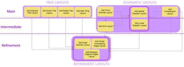
- There is no benefit to apply schematic layouts that preserve or try to preserve the current positions of the diagram features—for example, Linear Dispatch, Spatial Dispatch, and so on—before applying a tree layout, such as Radial Tree, Smart Tree, and Mainline Tree layouts.
- Partial Overlapping Edges and Reshape Diagram Edges layouts are often used as active refining algorithms and configured at the last position in the template layouts list
The below diagram outlines the recommended positions for the various layout types in the “active” layout sequence:
Rule and layout definitions specifics for subnetwork system templates
System diagram generation occurs in memory at the end of each subnetwork update process. The process retrieves all the network elements which belong to the newly updated subnetwork trace as input for the subnetwork system diagram generation. For this reason, diagram templates specified as subnetwork system templates for tiers must be configured in a different way than other diagram templates. In particular, subnetwork diagram template configurations must obey the following design rules:
- Forget the Add Connectivity Associations rule when configuring subnetwork diagram templates since connectivity associations are already part of the input features provided for subnetwork diagram generations.
- Since a subnetwork system diagram represents a subnetwork, avoid configuring its template with diagram rules that could add features which belong to other subnetworks when the diagram is built such as Trace, Spatial Query, and Expand Containers rules.
- On the other hand, to avoid creation of subnetwork system diagrams that strictly represent features in a subnetwork and don’t provide more value than subnetwork traces, set up subnetwork diagram templates with diagram rules that will simplify the subnetwork representation such as Reduce Junction, Reduce Edge, and Collapse Container rules.
What’s next?
Configuring network diagram templates is not rocket science. With these best practices in mind and after training on some test templates, you should quickly draw great benefits from Network Diagrams functions.
There are two interesting workflow videos that should guide you and get familiar with diagram template configurations: Customize Diagram Templates Using ModelBuilder and Create diagram configurations — Apply Map Symbols to Diagrams.
In the next versions, we are thinking about growing our diagram rule and diagram layout libraries. We also want to learn from you about your favorite diagrams, layouts and use cases. This would help enriching our experience and enhancing Network Diagrams in the way you want.


Article Discussion: