Introduction
Do network diagram edits impact the utility network? Do diagram layouts preserve at diagram update? Based on questions the Network Diagrams team frequently received, it’s time for a blog to talk about diagram feature geometries and editing in network diagrams in general. The sections below are to explain the impact of any geometry change on diagram features and show ways you can edit and manage network diagram content.
Diagram feature geometry
A network diagram represents a set of utility network or trace network features and network objects.
Every feature in a network diagram includes its own geometry. That is, a diagram junction exists in a network diagram with its own coordinates. In the same way, a diagram edge or a diagram container includes its own shape.

Moving a device or modifying the geometry of a line in a network diagram doesn’t impact the geometry of the corresponding feature on the utility network or trace network side.

Also, modifying the geometry of a device or a line in a network diagram has no impact on the same device or line represented in other network diagrams.

Edit diagram feature geometries
You change the geometry of diagram features each time you apply diagram layouts or use ArcGIS Pro editing tools on diagram features. You can also develop your own custom diagram layout or editing tools to edit the geometry of diagram features. Also, once you have created a network diagram you are happy with, you can use the Copy Layout tool. This will copy the layout to other network diagrams when they represent the same devices, junctions, lines, or objects. Below we discuss and show examples of these different tools and workflows.
Diagram layouts
We provide various diagram layout algorithms to lay out your network diagram contents and to change your diagram feature geometries—for example, Smart Tree, Reshape Diagram Edges, Force Directed, and so on.
You can configure these diagram layouts to run during the diagram generation process. You can also manually apply these layouts to any open network diagram on some or all of the diagram content.

ArcGIS Pro editing tools
In ArcGIS Pro, you can use the Move, Rotate and Edit Vertices tools to edit and reshape diagram feature geometries or adjust spacing between diagram features.
- Moving a diagram junction stretches all connected diagram edges.
- Moving a diagram edge moves its from and to diagram junctions and stretches the diagram edges that connect them.

- Moving any content diagram feature causes the related container to be redrawn around all its contents.
- Moving a diagram polygon container moves all its related content diagram features

Tip: To make your edits easier using the Move or Edit Vertices tools, you can turn on the editing reference grid on your diagram map like on any standard map. Then, you can also turn snapping on.

Custom diagram layouts and custom editing tools
Thanks to the NetworkDiagrams core assembly installed with the ArcGIS Pro SDK for the Microsoft .NET Framework, you can develop your own custom diagram layout algorithms or editing tools. Developing custom code allows you to finely edit diagram feature geometries and place each diagram feature as you expect. For example, you can compute the relative placement of devices that compose particular sets of selected devices or automatically place a given device according to the position of others. You can also determine the placement of given lines or devices according to some attribute values.
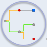
The images below show the same fiber splice closure diagram. On the first image, it displays with its initial layout. On the second image, you see the diagram arranged thanks to a custom diagram layout. This custom layout is coded as an ArcGIS Pro add-in using ArcGIS Pro SDK for .NET. It orders and places the fibers that come in and out of the hub terminator according to the fiber numbers.

Note: See our NetworkDiagram ArcGIS Pro Add-In Samples GitHub repository to learn more about how to develop your own custom diagram layouts:
- Fiber splice closure custom diagram layout add-in sample code
- Other custom diagram layout add-in sample code
In the animated GIF below, we show a custom ArcGIS Pro add-in command. This sample command allows you to horizontally align a set of selected diagram junctions using the ordinate of the pivot diagram junction to determine the horizontal alignment axis.

Copy layout
You can also use the Copy Layout From Diagram command to copy diagram layouts from one diagram to another. To use this command, the diagrams must be opened and represent all or part of the same network features and network objects.
The copy process applies to the active diagram that is considered the destination diagram. The process only operates on diagram features that represent the same network elements in both the source and destination diagrams. It copies the geometry of each diagram feature in the specified source diagram to the destination diagram.
When there are selected features in the active diagram, the command processes only the selected diagram features.

Edit attributes
On the sublayers under a network diagram layer, there is a join between the diagram feature class and the associated network feature class. This allows you to view both the diagram and utility/trace network attributes through the Attributes pane window or open attribute table.
However, you cannot manually edit these attributes, nor the attributes stored in the diagram edge, junction, or container class, nor those coming from the join with the associated network source feature class.
Nonetheless, there are a few exceptions when you go through custom code. On the network diagram side, you can develop custom code to edit the diagram junction Rotation attribute. On the joined network feature class side, you can change any editable attributes using custom code.
To learn more about attribute editing through network diagrams, see the two following sample add-ins available in our NetworkDiagram ArcGIS Pro Add-In Samples GitHub repository:
- Diagram junction rotation attribute editing through custom code
- Edit network feature attributes from a network diagram though custom code
Undo edits
Any edits even on temporary diagrams remain in your network diagrams. This means that you cannot discard, nor undo any layout changes in your network diagrams. The only exceptions concern manual edits operated using ArcGIS Pro editing tools on diagrams created in a mobile or a file geodatabase, or on published stored network diagrams in a branch version.
In addition, when you append network elements to a diagram or update a diagram, you never lose your network diagram layout. The Append to Diagram and Update Diagram processes always preserve the geometry of all diagram features that existed in the diagram before the operation and remain after.
Moreover, any stored diagram that you or any other user opens, always loads with its last saved layout regardless of who edited it.
Also, when you are consuming a utility network or trace network service and connected to a historical moment, you can search for any stored diagrams that existed at this moment and open them. In this case, any diagram features in the open network diagrams display with their saved geometry at this moment.
Conclusion
Through this blog article, we discussed various ways you can edit your network diagram content. In a future post, we will discuss how edits on your utility networks or trace networks impact your network diagrams.


Article Discussion: