In the first blog, we completed the first four steps to build an automation sample for Export Subnetwork using the ArcGIS Data Interoperability extension for ArcGIS Pro. As a refresher, below are the six steps to complete the workbench file.
- Generate Token
- Export Subnetwork
- Download JSON
- Split the JSON
- Feature creation
- Data transformation, schema setting, and writing the outputs.
We will focus on the last two steps of the process and complete the sample in this blog. After we finish the workbench file, we will create a Spatial ETL tool in ArcGIS Pro and embed this workbench file so it can be a part of your project.
Before we take a deep dive into feature creation, let’s learn the source of the output of export subnetwork on the note below. If you are familiar with the Utility Network API, feel free to skip this and move on to feature creation.
Step five, feature creation
The Export Subnetwork JSON output has all the information you need to build geometry when the resultTypes parameter includes the connectivity and featureElements types and the option includeGeometry is set to true.
We begin feature creation from the flattened and fragmented JSON output arrays of step four. There are three fragments from this JSON that has geometry – controllers, featureElements, and connectivity.
The inspection of these arrays show that we need to remove duplicates between the featureElements and the connectivity arrays. In addition, the featureElements array also includes system junctions where networkSourceId = 2 and that these objects do not have geometry. We will filter out these objects before we create geometry.
Using TestFilter transformers we determine the duplicate features and associations and the number of system junctions in our featureElements array.
Based on the screenshot below, Subnetwork RMT001 has 281 system junctions and that there are 128 associations and 2,971 features that are duplicates.

Now we are ready to create geometry for the rest of the objects of each array.
The geometry schema for controllers, featureElements, and connectivity arrays are different. So I created separate data flow for each fragment to build their respective geometries. In each data flow, using a FeatureMerger, we merge the spatialReference to each element so that they can be located in the world using the coordinate system in the feature after geometry is created.

A GeometryReplacer transformer is added to each data flow to create the feature geometry.
For the featureElements array, the geometry type of each feature could be either paths, rings, or has x,y, and z. The GeometryReplacer knows which geometry to create based on the geometry type.
For the connectivity array, we are interested only in objects with association connectivity where viaNetworkSourceId = 1. There is no geometry type in the array but each object has a pair of x, y, and z attributes – prefixed by from and to. Connectivity will be drawn with these coordinates as vertices using the VertexCreator. The association line will be drawn from these vertices using the LineBuilder transformer.
The controllers are point features and the geometry will be built from its x, y, and z attributes.
Using the CoordinateSystemSetter transformer, all features are tagged with the _coordsys attribute provided by the spatialReference object.
Below is the feature creation bookmark on my canvas.

Exclusions
If networkAttributes option is configured in resultTypes parameter, the results will appear as another array of key-value pairs in each feature of the featureElements array called networkAttributeValues. The sample has network attributes configured and a sample result is shown below. For this blog, I chose not to process them.

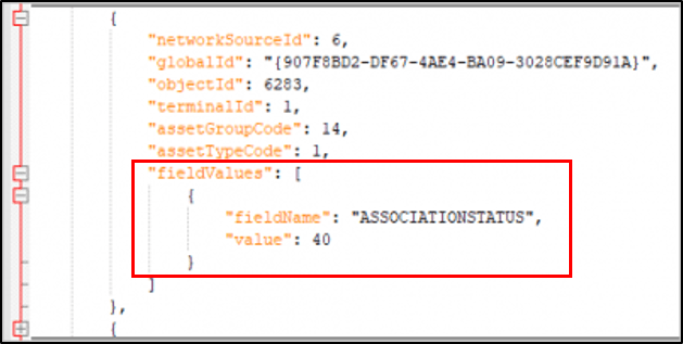
If fields options are configured in resultTypes parameter, a fieldValues array will be added to each feature with an existing value on the field, like below. As I mentioned earlier, I did not include fields in my export.
Note that the values for both networkAttributeValues and fieldValues are coded domains. To convert these coded values to description, another lookup process has to be added to this sample. Read the Extending the lookup table note for additional help with this process.
With a few attribute cleanup in the canvas, our features are now created. I’ve added a couple of Inspectors so we can view our output in the Workbench.
Our current workspace now looks like this:

When I test this workspace, the example results below are displayed from the Visual preview tab of the Workbench.

To see the geometry on a larger map, you can launch the Data Inspector with CTRL-ALT-D or by clicking on the Inspector icon on the left vertical tab of the Visual Preview window in the Workbench shown above.
In FME Data Inspector, Subnetwork RMT001 looks like below.

We are getting close but we are not done yet! If you look at the table displayed above in the FME Data Inspector, you will notice that our attributes still show the coded domains. We need to change these to descriptions, set and modify the schema to make our output dynamic, and finally write the output to finish our sample.
Step six, data transformation, schema setting, and writing outputs
In a recent GeoNet article, our solutions team shared a toolbox for Adding Descriptions to the Export Subnetwork JSON. It includes a tool to create a lookup table and another tool to update the JSON output(s) of the Export Subnetwork with descriptions. This step follows the same patterns as the toolbox built in Python; however, in our sample, the lookup table is generated during run time to make the lookup table dynamic with regard to schema changes.
Before we build the lookup table, it is important to understand, the Source Mapping object from the JSON result and the data element of the utility network feature layer. If you are already familiar with these, feel free to skip the next two sections and proceed to Build the lookup table.
Source Mapping
The sourceMapping object from the _jsonOutput attribute is a table of unique network source ids and their corresponding feature class names in the geodatabase. Below is a sample of the source mapping array for subnetwork RMT001. Only unique networkSourceId from exported features in the featureElements array are found on this JSON object.

We need source mapping to group features by feature class names before we write them to the output and also as a reference for our lookup table to retrieve asset group and asset type values from the data element of the utility network.
Query Data Elements
The data element of the utility network is a repository of its rich metadata. In ArcGIS Pro, right-click the utility network layer in the Contents pane and click Properties to access the Layer Properties dialog, then click on the Network Properties tab, to see the dialog below.

Most of the network properties that you see in this dialog come from the JSON return of the query data elements of the utility network feature layer.
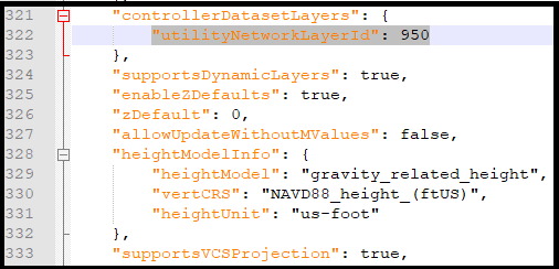
With the REST API, the utility network properties are returned using query data elements on the utility network feature layer. For my sample below, I entered [950] for the Layers: textbox, to query the data element of the utility network. If I don’t add a layer Id, the query will return the data elements of all layers of the feature service. To retrieve this layer id from a web query, see the Work with the utility network feature server note below.


From the JSON result above, junctionSources and edgeSources (not shown) arrays in the data element have sourceId, layerId, assetGroupCodes and assetTypeCodes and their corresponding descriptions. We will need these as references for our lookup table.
The utility network data element contains a large amount of metadata and it is up to you to identify what you need for your own workflows.
We will follow three tasks in this last step to add into our workspace. These tasks are data transformation, schema setting, and writing the outputs. Let’s begin with data transformation.
Data transformation
We start this step by building a lookup table, that will be a reference table to convert coded domains to descriptions later in our data flow.
In our current workspace, we create a new data stream after the generate token bookmark by adding three web queries. The purpose of each web query is described below. The details on why we need the results are explained later in each task.
- The first is to identify the layer ID of the utility network feature layer
- The second to retrieve the utility network data element
- The third one is to retrieve the feature layers’ properties in your feature service.
Below you can see the three web queries I mentioned, preceded by Generate Token.

Our first web query identifies the utilityNetworkLayerId of the feature service. We will use the pretty JSON (pjson) output format of the utility network feature service to retrieve this attribute. Retrieving the system generated utlityNetworkLayerId from the data element makes our sample dynamic.
The purpose of the next query is to retrieve the utility network’s data element. With the utilityNetworkLayerId from the first web query, we pass this value as a parameter for the second web query – QueryDataElement operation of the FeatureServer service. With the data element in our data flow, we expose domains, layer Id, source Id, and the JSON fragments that have the asset groups and asset types for each junction and edge source. These JSON fragments will be parsed later downstream.
The third web query will be used to retrieve the data elements of the feature layers that participate in the feature service so that we can add the feature layer names and aliases to the features of the featureElements array of the JSON output later.
Using the FeatureMerger transformer, we merge the results of the last two web queries by layerId, and with several transformers shape the data and a few attribute cleanups, our lookup table from the data elements are done. We still need to add one more item of metadata from sourceMapping.

The sourceMapping array has the feature class names of the network sources which we need for our output feature types. I merged this array to the lookup table for a final lookup table. Just to tidy my canvas a bit I used a tunnel – dotted connectors – from the sourceMapping Array to the FeatureMerger.

Our lookup table is now complete and has descriptions and aliases as shown below. This table is now ready for mapping with the feature elements

Attribute transformation
Using the lookup table as a reference, we merge all the features from featureElements, controllers and connectivity arrays by networkSourceId, assetGroupCode, and assetTypeCode to map coded domains to descriptions.
After some cleanup of a few attributes to match the desired schema, I filtered or grouped the features by jsonOutputArray using the AttributeFilter.
This simple transformation is shown below.

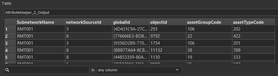
If you run the solution up to this bookmark, our feature layer attribute table should look like the below example – with all codes replaced by user-friendly descriptions. Now we can set the schema by JSON output array and write the desired outputs in the next task to finish this workbench file.

Schema Setting and Writing the Output
We need to set the schema for each JSON array before we write the output. I want to make my workspace dynamic enough for readers who would like to try the sample using their own services. For this task, I used a special custom transformer in Data Interoperability called SchemaSetter. This transformer can be downloaded directly from the canvas. Just start typing the name and auto text will filter down to this transformer.
I included four formats in this sample for my output:
- JSON
- FGDB
- SHP
- GeoPackage
Below is the bookmark for these final tasks. The JSON output which you do not see in this bookmark is the JSON result from Export Subnetwork, previously done in step three. I also added a FeatureWriter transformer for each of the three output formats I wanted to write.

Each FeatureWriter is configured with schema from the SchemaSetter and the appropriate feature classes created from the controller, featureElements, and association arrays. To set the schema from the previous task to your output, check the box for the Dynamic Schema Definition parameter and configure as shown in the sample below.

The featureElements array has an additional setting in the Feature Class or Table name parameter which is set to the value of feature class name – @value(featureClassName). This will set the writer to group features by feature class, shapefile, or whatever the case may be for the selected output format. This advanced technique uses what is referred to as Dynamic Workflows. Only the System Junction object table needs to be configured manually because its schema was not set to be dynamic.
With a single data source from the Export Subnetwork JSON output, you can write into different output formats with different schema requirements for multiple external systems with Data Interoperability. One output can be for your mobile app in OGC Geopackage, an FGDB can be the source for your operational (read-only) enterprise geodatabase, or maybe even shapefile. You could even write directly to feature layers in your portal.
Our completed workbench file now looks like the below example.

Running the sample
Now I can hit the Play button from the ribbon to run the workbench. After the workbench runs successfully, the four output types are written in a folder named by the output formats – shp, gdb, gpk, and json.

When you run the entire workspace for the first time, it opens a dialog prompting the user to pick a feature service URL from a drop-down, and to type SubnetworkName, username and password on the provided text boxes, as shown below. Data Interoperability refers to this dialog as a user parameter. To protect your password make sure that the Save as User Parameter Default Values is unchecked.

Parameters appear from a dialog in the workspace during run time prompting users to enter values or pick from a drop-down list of choices for convenience and prevent user errors.
Using parameters in my workbench, allow me to run the tool on different utility network feature services. You can configure your own choices for the Service parameter by right-clicking on the parameter in the Navigator pane, User Parameters list in Workbench and clicking the Edit Definition context menu item.

This Service parameter is configured with a Choice parameter type. In the image below you can see that I have three sample utility networks with this Service parameter definition.

Download the sample
You can download the workbench file sample here to try this yourself. Read the note below before you run the sample. Run your workspace by steps and inspect your results often, until you can run the whole workspace in your canvas, and it writes the expected output.
Using Spatial ETL
Our final task for this blog is to create a Spatial ETL tool to make it part of an ArcGIS Pro Project or package by importing the workbench file. After I created my ETL tool, I can then run it from the geoprocessing pane or use the Scheduler option. The help documentation outlines the process to create a new Spatial ETL tool referencing an existing FMW file here.
Summary
This completes our blog. In the first part, I explained four of the six steps to build our sample solution. I shared valuable information about Export Subnetwork and how to download and parse the JSON return of the tool. In this second part, we completed the sample with the last two steps and I discussed the JSON output of export subnetwork in detail, working with the feature service of your utility network and its data elements, feature creation including geometry from JSON and changing coded domains to user-friendly descriptions, and dynamic writing to multiple outputs. Overall I showed how to build an export subnetwork automation tool using the Data Interoperability extension of ArcGIS Pro. Lastly, I showed you how to run & configure parameterized workbenches and how to use the Spatial ETL toolbox in Pro. This workbench file is now ready for further automation to export all subnetwork of any utility network…which will be the topic for my next blog.
I hope you made it this far and found the blog informative and helpful. Please leave comments below with any questions on the sample provided or with Export Subnetwork itself.
Card and Banner images by:


I can’t download the sample workbench. It says “This link is only available to internal users”. Could you please fix it?
Apologies for the difficulties Yukihisa, I’ve updated the link and you should be able to access now. Thanks!