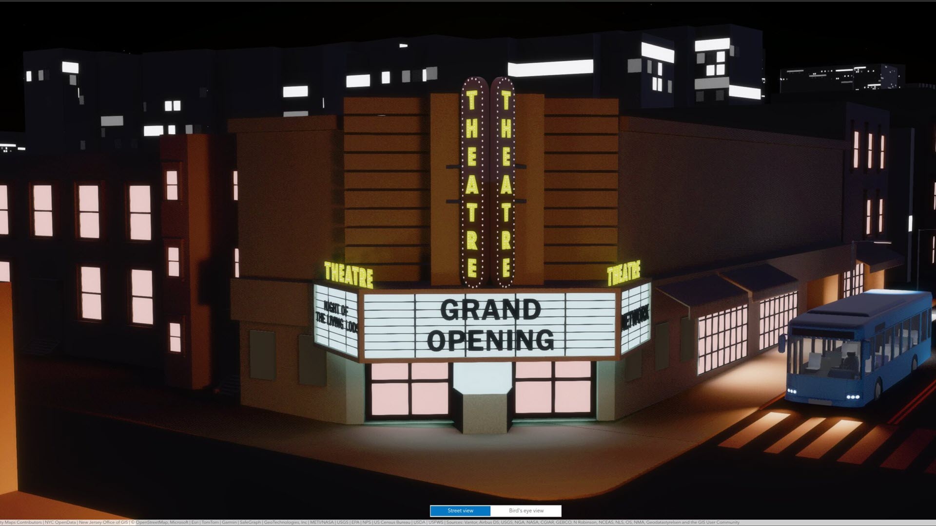
Until version 5.1, ArcGIS Maps SDK for JavaScript did not support emissive materials and used a rudimentary fallback implementation for scenes with transparency on a subset of mobile devices. Most notably, many iPhones and iPads were affected. In the 5.1 release, we bring their visual quality much closer to other platforms. The new release ships with an algorithm based on standard 8-bit integer textures, works across all devices, uses only 60% of the memory of the previous approach, and produces very similar visual results:
In JavaScript Maps SDK, we use order-independent transparency (OIT) to render transparent objects. OIT produces a reasonable approximation of the correct transparency, is simple to implement, and performs well in WebGL. This algorithm relies on accumulating color and alpha values into floating-point textures. This accumulation requires the EXT_float_blend WebGL2 extension, which is not available on a significant subset of iOS devices. Furthermore, the float16 textures used in our 5.0 implementation use up a lot of valuable memory which can cause instabilities on mobile devices.
RGBA8 Order-Independent Transparency
Meet OIT8, our implementation of order-independent transparency using only RGBA8 textures: We use the 8 bit storage as a fixed-point representation, and apply the same blending operations as with the 16 bit floating point textures. This algorithm relies on WebGL2 core functionality only, and therefore works on all devices.
The first step is to “compress” the computed fragment color by dividing it with a fixed ratio (we use 16) before writing it to the framebuffer. During the OIT compositing step, we then read the accumulated results and multiply it by this factor. This gives us a usable fixed point value range of 0..16, with 4 bits of precision per written fragment (i.e. the color value of a single surface). Everything else in the rendering pipeline works the same as with floating point textures.
This compression, however, is not a magic bullet, as it creates two new problems: color banding due to the reduced per-fragment resolution and colors shifting towards white on high overdraw areas due to the limited value range.
Addressing Color Banding
Color banding happens since we now have a reduced color resolution due to the fixed point compression. One can immediately notice this banding on smooth color transitions:
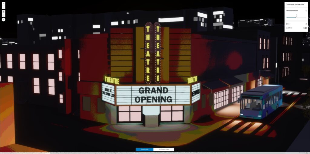
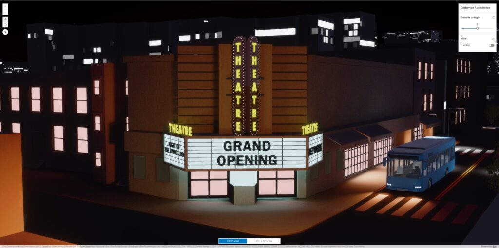
We address this banding by dithering the output colors using a small amount of noise. This dithering noise is randomized using the pixel position, both in screen space and in depth. Since transparent objects blend against other objects, this dithering is barely visible, as it blends into the background:
Addressing Clipping Artifacts
When we run out of the value range of 0..16, which may happen after 16 overlapping transparent surfaces, the pixel values overflow and are clipped when written to the texture. This causes all colors to shift towards white in these areas. In this scene you can observe this in the tree foliage in the back of the street:
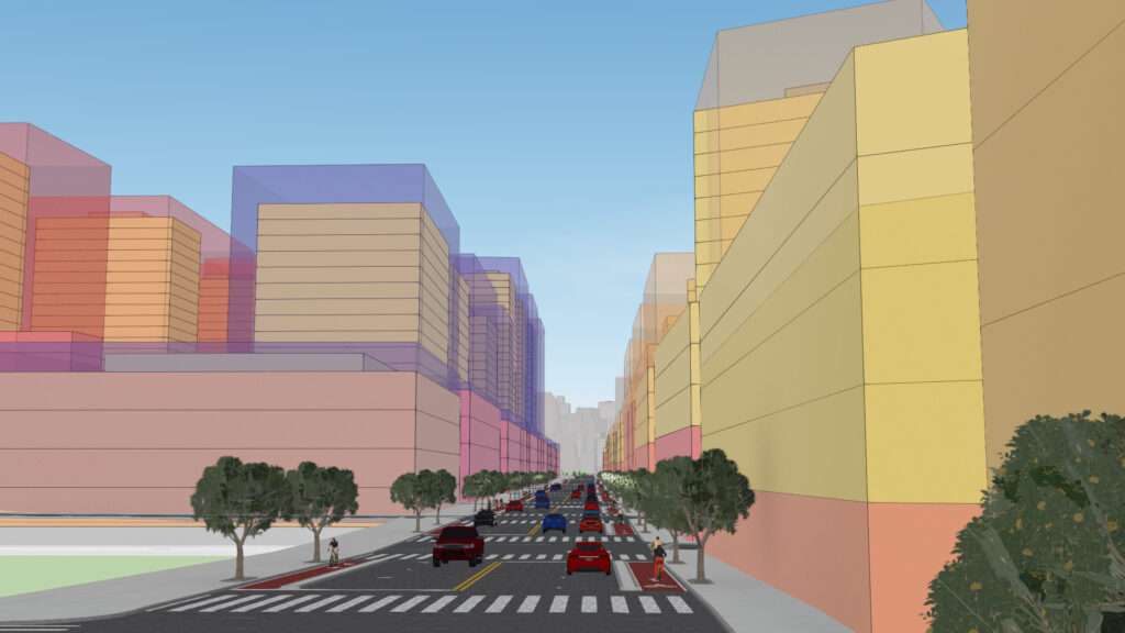
This white shift happens only in areas with a lot of overdraw and when the transparent content fully covers everything behind. In these areas, an observer cannot really distinguish what’s going on spatially anyway. We can exploit this, by gradually only showing the front-most surface color when the alpha channel starts to saturate. This restores the color to a good approximation of all the blended surfaces, and our trees look nice again:

Emissive Materials using RGBA8 Textures
In version 5.0 of JavaScript Maps SDK, we did not support emissive materials on devices that lack the EXT_float_blend WebGL2 extension. In 5.1 we add support by using the same 8 bit fixed point representation as for transparency to implement emissive rendering and glow.
Our rendering pipeline for light-emitting materials supports high-dynamic range values, where emitters can be brighter than a standard material. Similar to transparency, emission information is stored in additional floating point textures during rendering. In scenes with transparency and emission these buffers end up using 30 bytes per pixel, or about 110 MB on a 11 inch iPad.
On these devices, we store emission information using the same fixed point representation in RGBA8 textures. Naturally, the emissive buffer also observes banding, but the fix is the same as for transparency — adding dithering. Because our emissive strength is limited to 16, we do not run into the clipping issue we have for transparency.
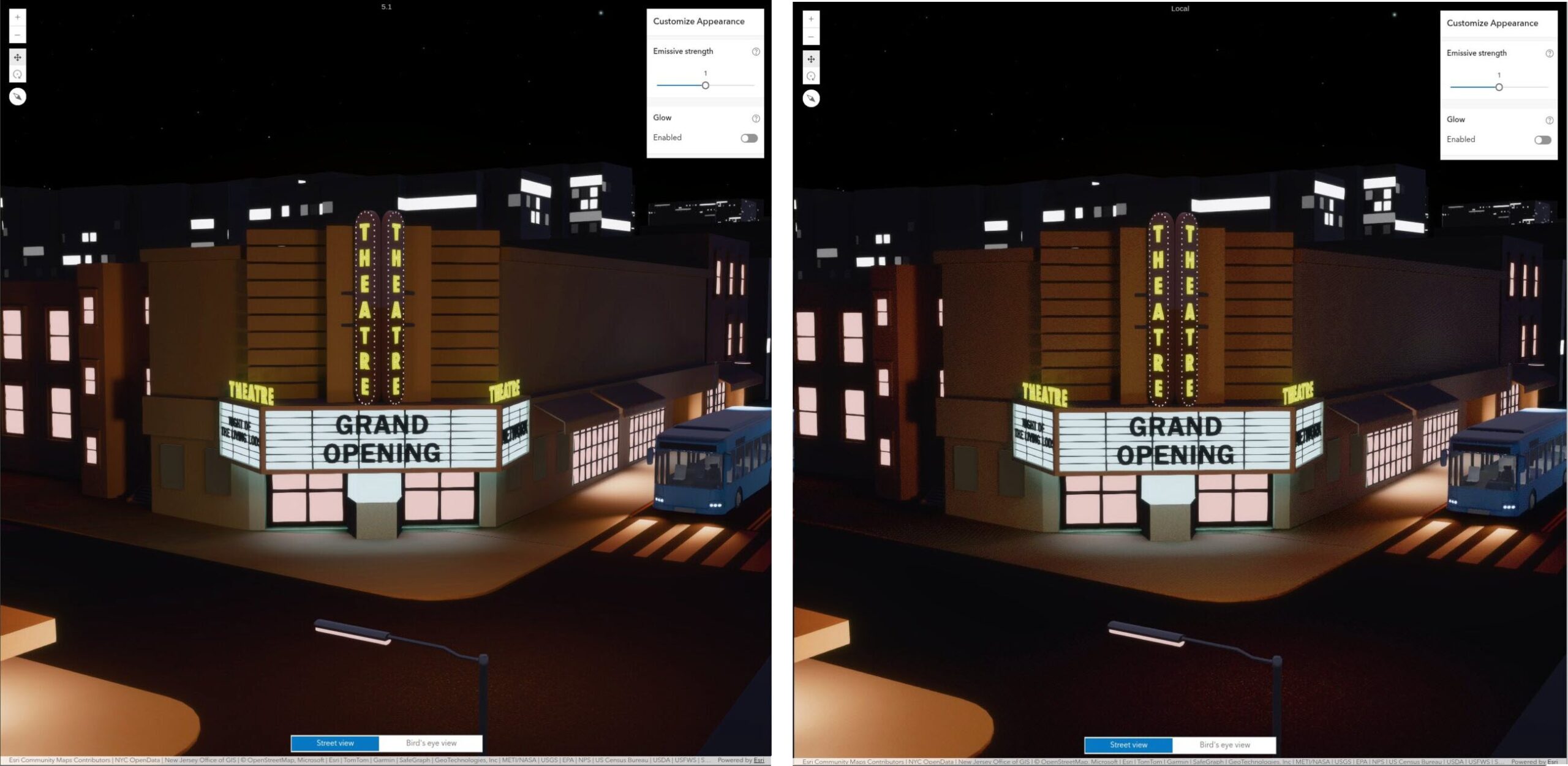
Light emission, however, is blended with transparent geometry. For example, a white light source behind a red transparent surface appears red. Since our RGBA8 pipeline only has about 4 bits of information for each, this becomes sensitive to color shifts, which will make the scene render slightly different on these devices, as shown here:
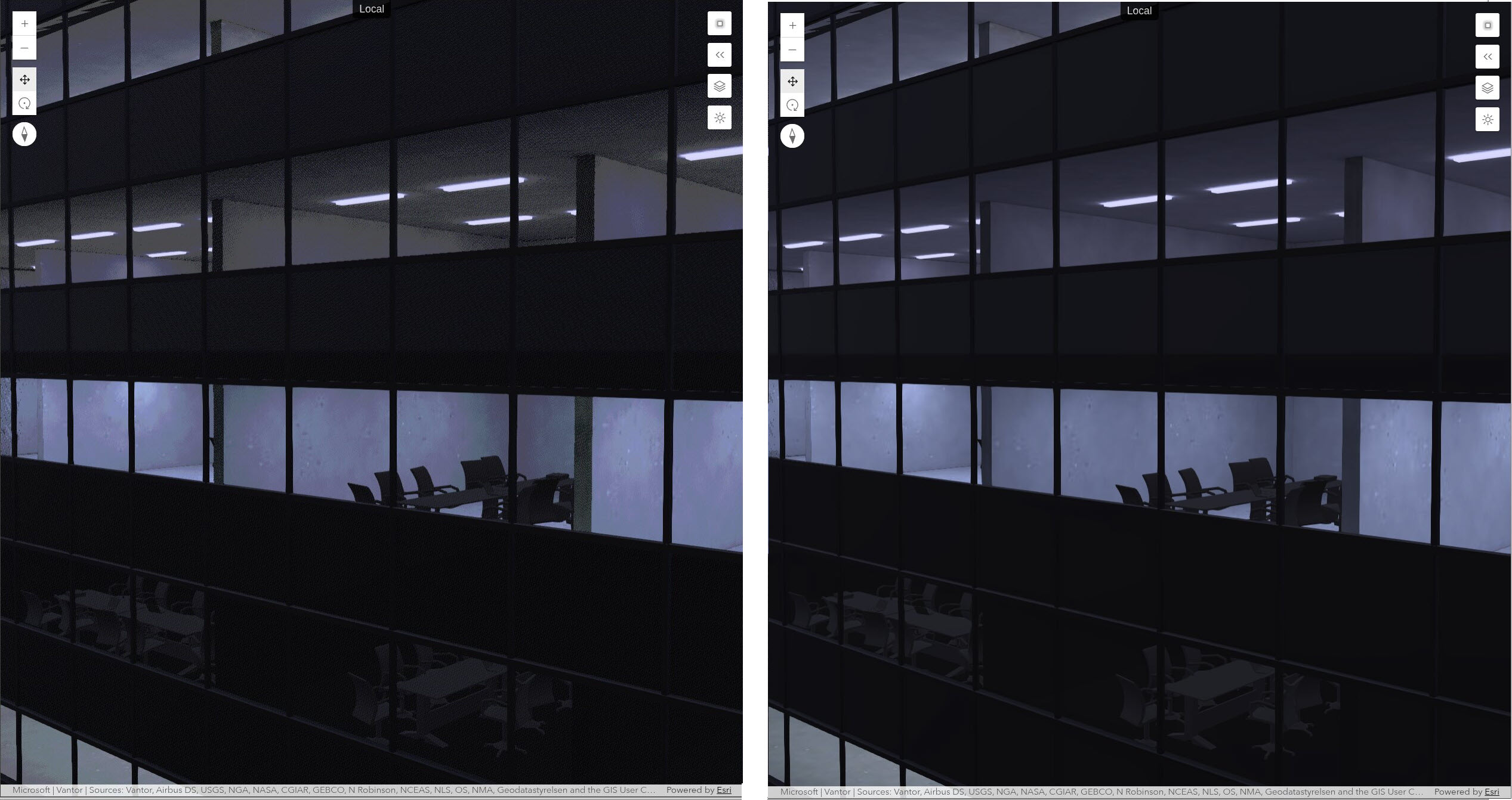
Given that we have only 4096 colors available for both the emission and the transparency, this is still a very acceptable result, and much better than not supporting emission at all on low-end devices.
Conclusion
We are excited to bring full transparency and emissive material support for all devices in version 5.1 of JavaScript Maps SDK. No changes are required to existing applications; these improvements work automatically with all web scenes. Even limited devices will be able to show most scenes virtually the same as more capable hardware.
To learn more about emissive material support, try out the hands-on sample, Visualizations with light-emitting symbols.
We are striving to bring even better visuals for realistic and stylistic visualizations using light emission and transparency in the next versions — stay tuned! To stay up to date, you can subscribe to the ArcGIS JavaScript Maps SDK Blog and subscribe to @EsriDevs on YouTube to watch for video posts and livestreams hosted by Esri’s JavaScript Maps SDK team.
For more information on version 5.1 of JavaScript Maps SDK, see the blog ArcGIS Maps SDK for JavaScript: What’s New in 5.1 or the release notes.
If you found this post interesting and have a passion to help developers build great real-world mapping apps, be sure check out our job openings at Esri Careers.