ArcUser Online
Creating and Texturing Multipatch Features
Learn basic techniques for creating 3D buildings
By Craig McCabe, Esri Mapping Center Team
This article as a PDF.

Figure 1: This exercise shows how to correct this sampling error, commonly seen in high-resolution DEMs in urban environments.
The 3D virtual city is emerging as an essential GIS tool for visualization and analysis in the urban environment—from placing a proposed building construction in the context of its surroundings to conducting analyses in three dimensions such as line-of-sight or 3D volumetric shadows. The multipatch, Esri's native 3D feature type, is a key element whether working in ArcGlobe or ArcScene. ArcGIS 10 introduces a host of new 3D data management and analysis capabilities that enhance 3D analysis.
This exercise walks the reader through the process of creating and adding texture to a 3D multipatch feature. It uses a geometrically simple urban feature—a freeway overpass in downtown Philadelphia—and starts with a polygon and some high-resolution aerial imagery. The workflow outlined will familiarize the reader with tools in ArcGIS 10 for importing, exporting, and placing different types of 3D features.
It's assumed that the reader is familiar with ArcGIS Desktop applications and the ArcGIS 3D Analyst extension, including ArcGlobe. Some familiarity with Google SketchUp may also be helpful. To complete this exercise, the following software and data are required
- ArcGIS 10 with the 3D Analyst and Spatial Analyst extensions
- Google SketchUp 8 (free version available at sketchup.google.com/download/)
- Multipatch Overpass data .zip file on ArcGIS.com
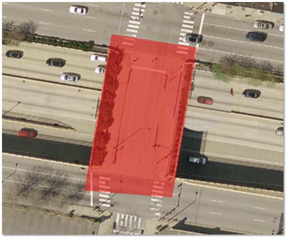

Figure 2 (left): Add the polygon feature created in ArcMap to Overpass.3dd.
Figure 3 (right): By default, the polygon will drape over the globe surface like a blanket.
The 16-step workflow is organized into four sections:
- Extruding an overpass polygon and exporting it as a 3D multipatch feature from ArcGlobe
- Extracting aerial imagery to use as a surface texture
- Applying the extracted imagery to the overpass in SketchUp
- Importing the newly textured overpass back into ArcGlobe
Exercise Overview
This exercise starts with an overpass feature that has been poorly captured by the existing 1-meter (m) digital elevation model (DEM) for downtown Philadelphia as shown in Figure 1. This type sampling error is commonly seen in high-resolution DEMs in urban environments that show overlapping roadways and structures of different elevations. Lower-resolution DEMs, by comparison, just make features look flat. One approach to correcting this situation might be to edit the DEM or add a patch to raise that road and create a flat surface. Although this fixes the elevation of the overpass road, it creates an impenetrable wall in the underlying expressway.
Instead of editing the DEM, this tutorial will show how to create a simple but realistic-looking overpass as a 3D multipatch feature that spans the gap and has a void space underneath. This process requires a polygon file and a swatch of high-resolution imagery. SketchUp will be used to apply imagery to the top of the 3D overpass model.
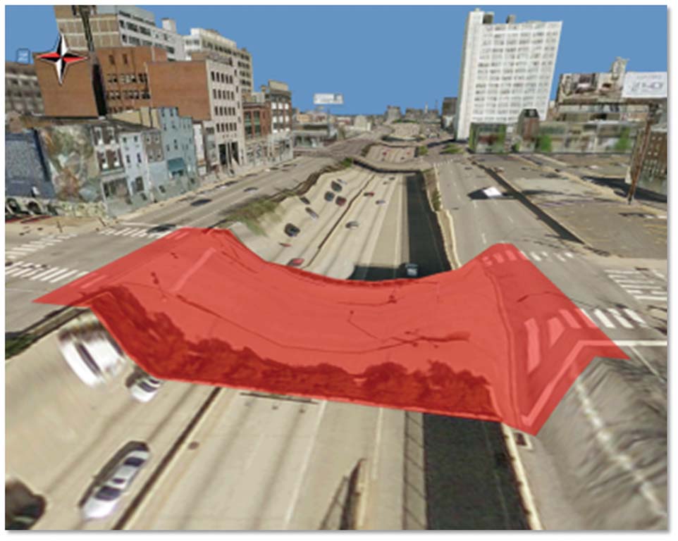
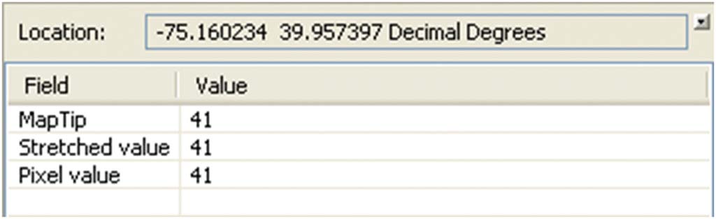
Figure 4: To determine the elevation of the overpass once it's extruded, sample the value of the DEM on each end of the roadway (as indicated by the ovals).
Section 1: Create a 3D Multipatch from an Extruded Polygon
- The first step is to create a polygon feature using ArcMap in universal transverse Mercator (UTM) Zone 18N. Later, this polygon will be extruded to create a 3D volume for the overpass. After adding the imagery file in the Overpass geodatabase to an ArcMap document, create a simple rectangular shape and ensure that there are small areas of overlap at each end of the overpass. (The completed polygon feature is overpass_ply and is included in Overpass.gdb.)
- Close ArcMap and open the ArcGlobe Overpass.3dd file. Add the polygon feature just created. By default, the polygon will drape over the globe surface like a blanket. Ensure that the polygon completely spans the roadway below as well as part of the elevated road surface on each end so there are no gaps when the polygon is extruded to 3D.
- To correctly place the elevation of the overpass once it's extruded, sample the value of the DEM on each end of the roadway (as indicated by the ovals shown in Figure 4). Use the Identify tool to sample the elevation, with 1-m DEM specified as the Identify from layer. Both sides of the overpass will have an elevation value of about 41 feet.
- To set the elevation of the overpass polygon, open the Layer Properties > Elevation tab and select the Floating without a surface option. Input a constant offset value for the desired elevation in the text box in the lower right side of the Layer Properties dialog box as shown in Figure 5. The DEM is 41 feet (this is pretty close to 12 meters), and this height bridges the gap well.
- With the base elevation determined, an extrusion of 2 m is applied. To ensure that the top of the overpass matches the road surface on each side, use either an elevation of 12 meters and a -2 extrusion or an elevation of 10 meters and a +2 extrusion.
- Next, use the Layer 3D To Feature Class tool in the 3D Analyst toolbox to convert the extruded 3D polygon to a multipatch feature. (Use overpass_mp to skip this step.)
- Now the 3D multipatch feature needs to be converted to a COLLADA format file so that it can be imported into SketchUp to apply the imagery. This is done using the Multipatch To COLLADA tool in the Conversion toolbox, which outputs the COLLADA file to a specified folder.
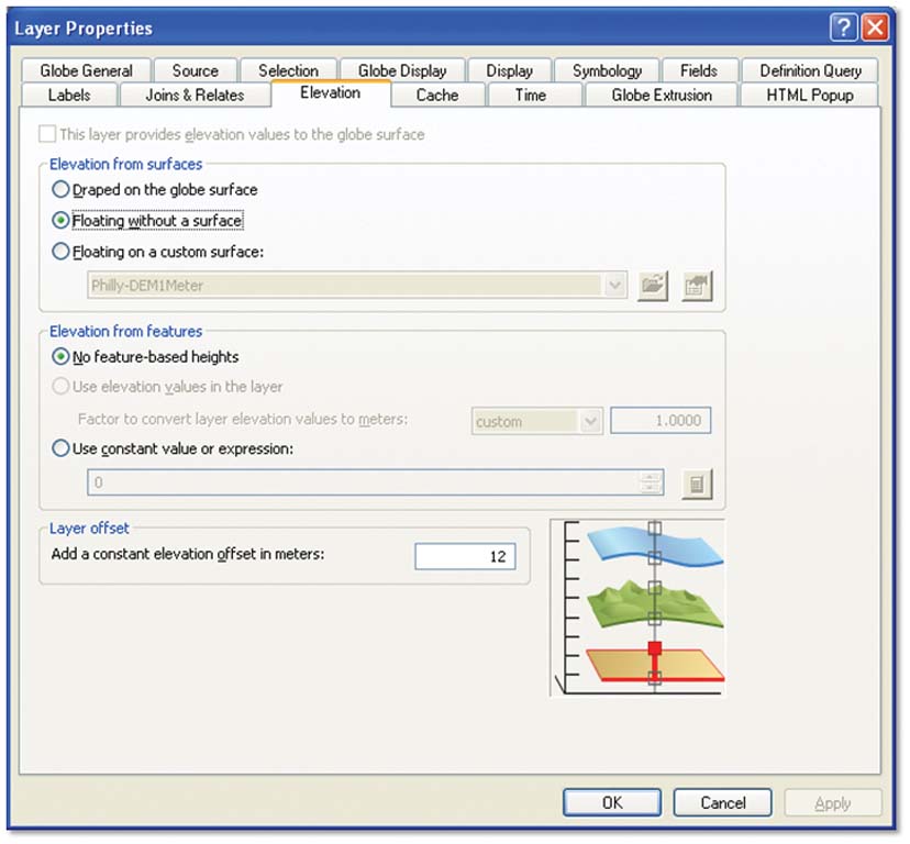
Figure 5: Set the elevation under Layer Properties.
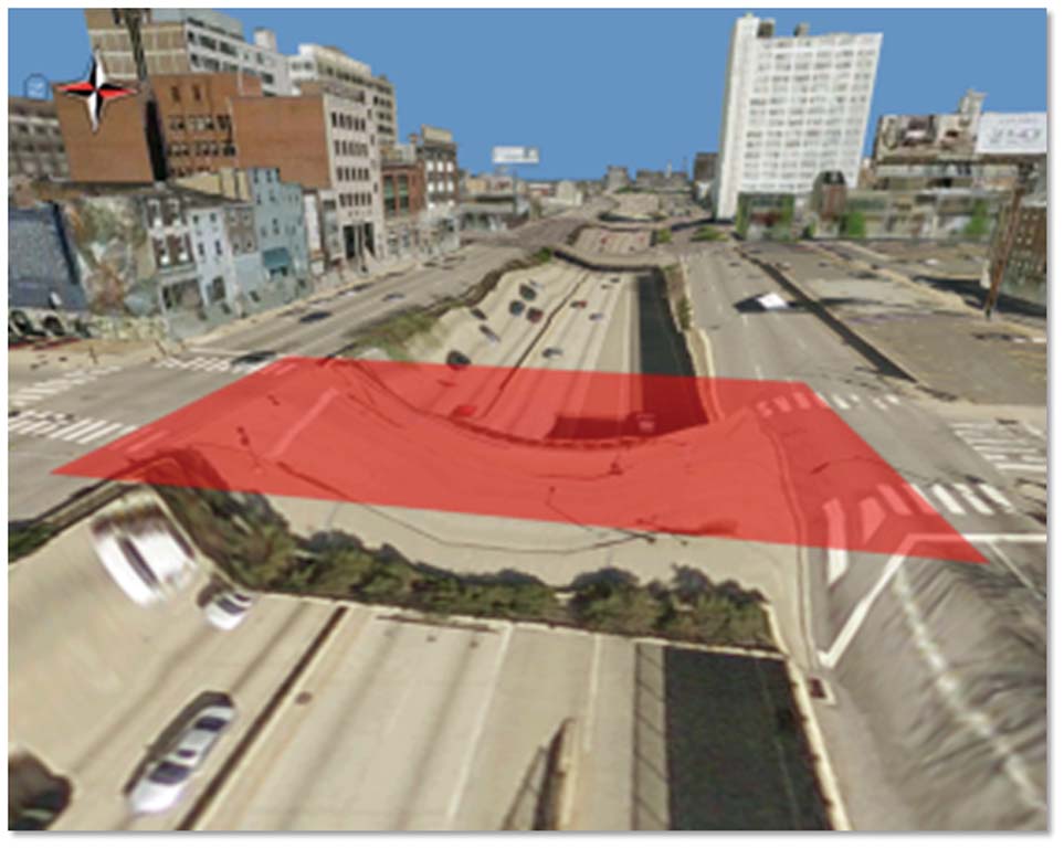
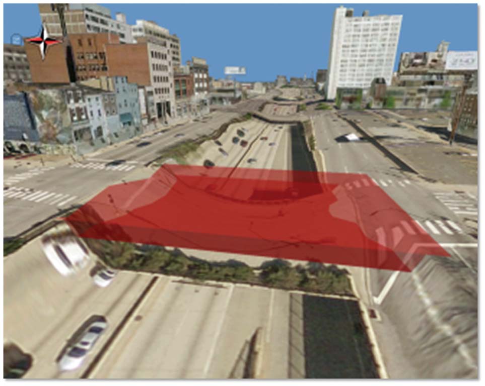
Figure 6: Use the Layer 3D To Feature Class tool to convert the extruded 3D polygon (left) to a multipatch feature (right).
Section 2: Extract Surface Imagery
- Use the Extract By Mask tool in the Spatial Analyst toolbox to extract imagery for the top of the overpass. The parameters for this tool include the imagery swatch as the input raster and the overpass polygon as the feature mask. (The imagery_extract file can be used to skip this step.)
- Next, convert this extracted imagery to PNG format using the Copy Raster tool in the Data Management toolbox. The input raster is imagery_extract, the output raster is imagery is PNG and the pixel type is 8-bit unsigned.
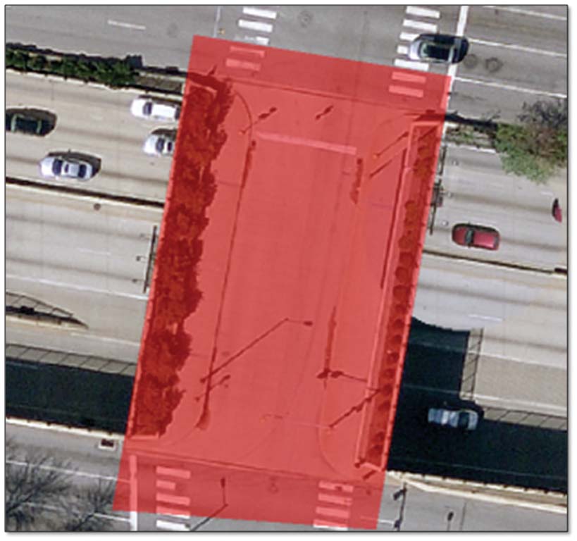
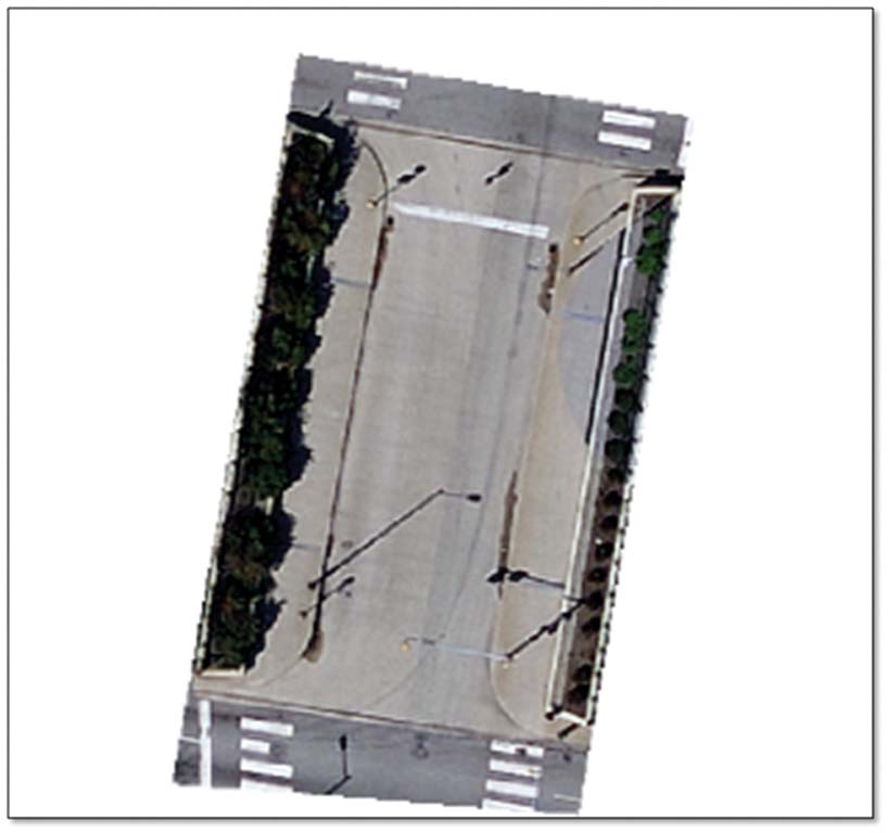
Figure 7: Use the Extract By Mask tool in the Spatial Analyst toolbox to extract imagery for the top of the overpass.
Section 3: Apply Surface Imagery and Color to the 3D Overpass in SketchUp
- Open SketchUp and use File > Import to import the COLLADA model (*.dae) saved in Step 7. Use the Select tool to select the model, then right-click and select the Explode option.
- Activate just the top face of the overpass with the Select tool. Use File > Import, select the *.png file type, then navigate to the PNG imagery exported in Step 9. With the Use as texture option enabled, roughly place the image on the top face (don't worry about the exact placement for now).
- With the top face still selected, finely adjust the position of the imagery by choosing Edit > Face > Texture > Position. Four pins will appear at each corner of the image. Move each pin to the four edges of the overpass and stretch the imagery until it fits.
- With the imagery in place, use the Paint Bucket tool to apply color to the sides and bottom of the overpass. (Color_C15 in the Materials palate roughly matches the color of the concrete.)
- Once the imagery has been added and painted, export the model (File > Export > 3D Model) back to a COLLADA file, which will then be used to replace the untextured multipatch in the ArcGlobe document. [Note: SketchUp version 6 format may be used in place of COLLADA for this step (File > Save As > SketchUp Version 6).]

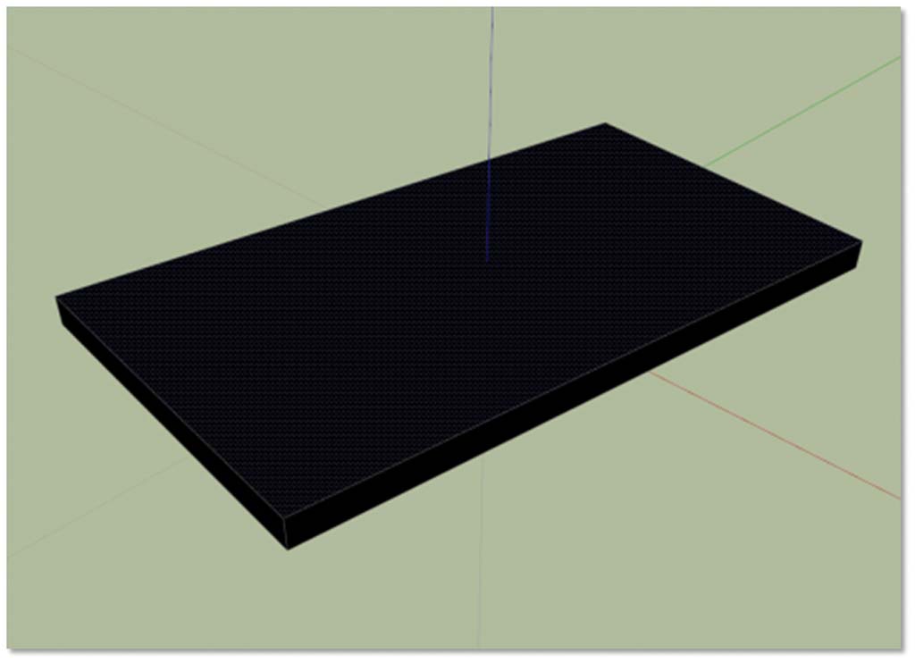
Figure 8: In SketchUp, use the Select tool to select the model, then right-click and select Explode.
Section 4: Importing the Textured Overpass Back into ArcGlobe
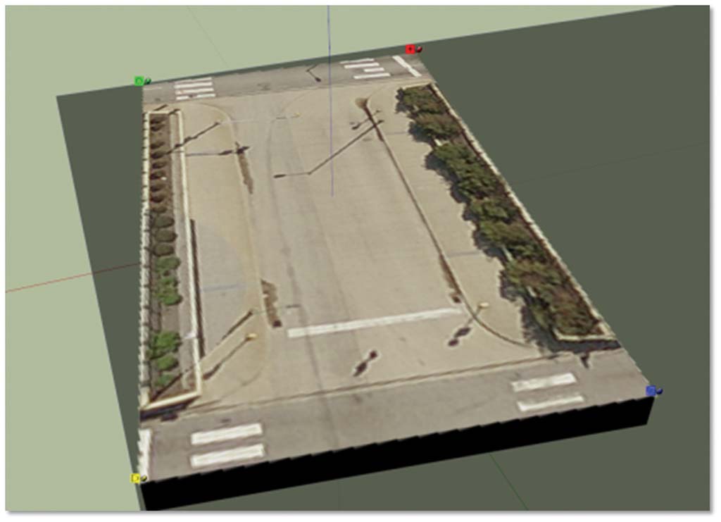
Figure 9: Move the four pins to the edges of the overpass and stretch the imagery to fit.
- In ArcGlobe, begin a 3D editing session. Use the Edit Placement tool on the 3D Editor toolbar to select the overpass. While the overpass is selected, use the Replace with Model function in the 3D Editor toolbar and navigate to the COLLADA (or SketchUp) file saved in Step 14. (A textured COLLADA file is also provided in the 3D Models directory in the ZIP file.) After the file is selected, save the edits. The newly textured overpass will appear in place of the untextured version (The textured multipatch supplied in the Overpass.gdb is overpass_mp feature.)
- As a final touch, add shadow underneath the overpass to mask the duplicate imagery on the expressway below. A copy of the original overpass polygon was adjusted to be slightly narrower on each side so that the shadow doesn't appear on the upper road surface edges. (Use shadow_ply in the Overpass geodatabase.) An 80 percent black fill is applied (CMYK=0,0,0,80) along with a 10 percent transparency. The finished product, compared with the original image, is shown in Figure 12.

Figure 10: Use the Paint Bucket to color the sides and bottom of the overpass.
Conclusion
This exercise outlined the basic steps and tools needed to create a textured 3D multipatch feature in ArcGIS 10. The workflow is simple, but the techniques for feature extrusion, multipatch creation, and texturing can be applied to create complicated 3D structures such as bridges, houses, or high-rises. If just 3D analysis is the goal, skip the texturing steps and see the ArcGIS Resource Center help topic "Obtaining elevation information for building footprints" to learn how to quickly create a city's worth of 3D multipatch buildings from footprint polygons with height attributes.
Visit the 3D GIS Resource Center and 3D GIS blog for tips on working with and analyzing 3D data in ArcGIS, and video demonstrations highlighting the different types of analysis possible in ArcGIS 10, such as volumetric shadow analysis over time, 3D feature extraction from LiDAR, and 3D viewshed analysis. Download additional 3D templates and workflows from the 3D Template Gallery. The 3D City: Philadelphia template is particularly useful for those new to virtual cities in ArcGlobe. It includes a collection of highly detailed 3D building models, vegetation, and street furniture for downtown Philadelphia, Pennsylvania.
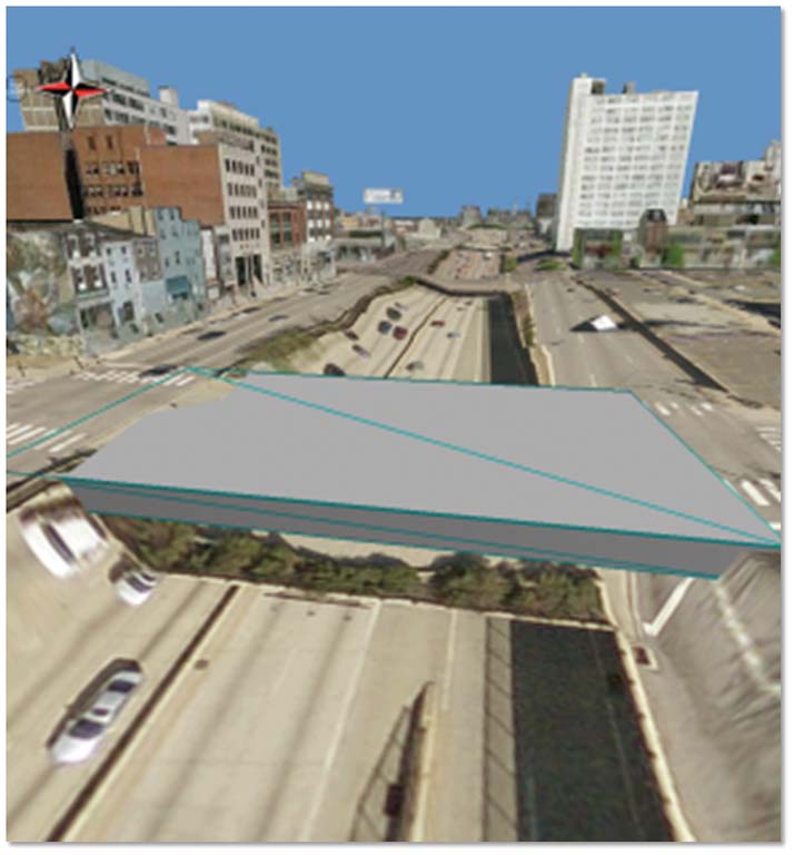
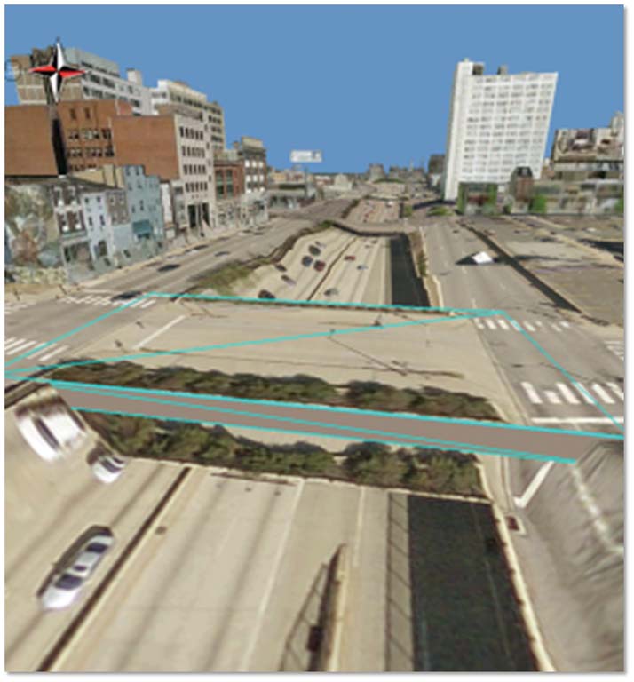
Figure 11: Use the Edit Placement tool and the Replace with Model function in the 3D Editor toolbar to add the COLLADA (or SketchUp) file.
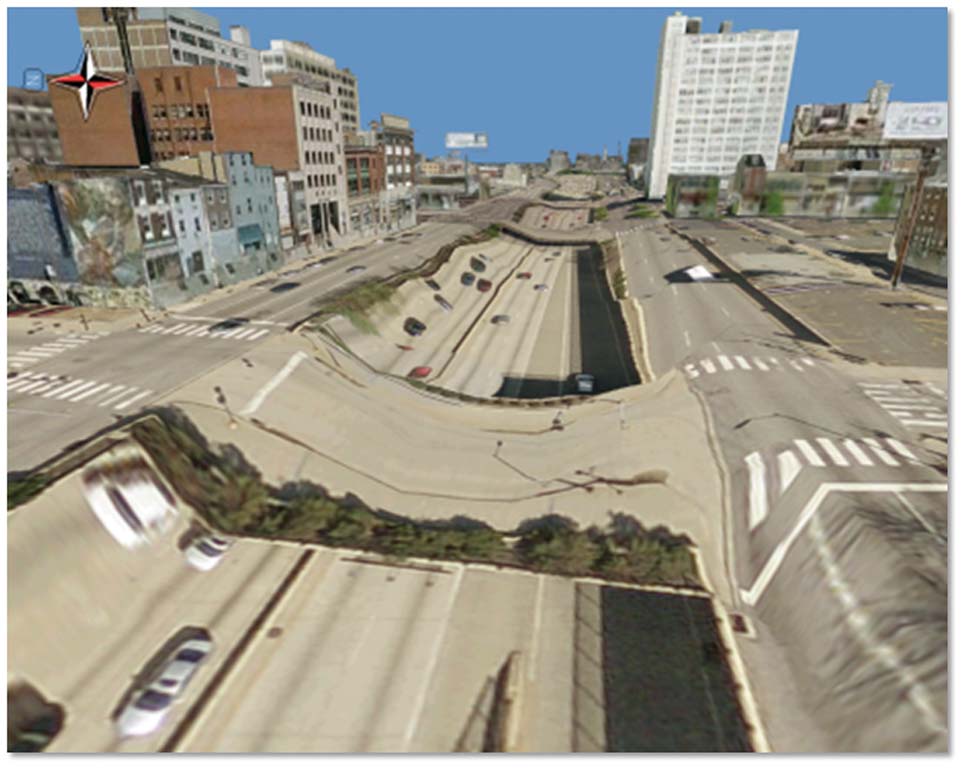
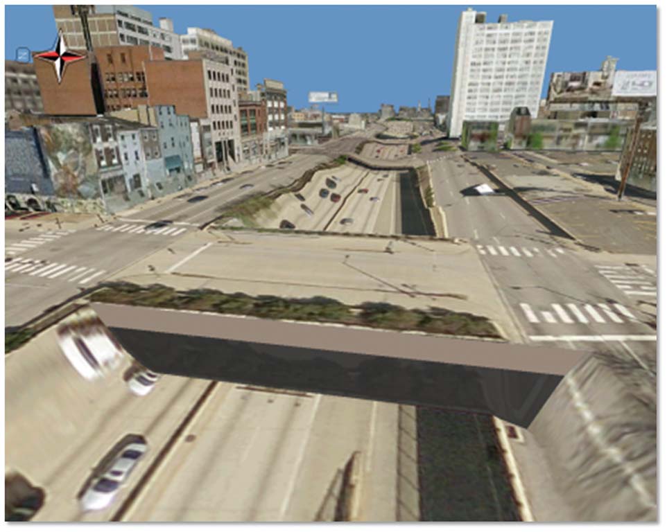
Figure 12: Now compare the overpass in these before (left) and after (right) images.