This workflow is for ArcGIS Pro 2.9 or later.
Adding Revit and or IFC files to GIS scenes provides a comprehensive view of the built and natural environment. To use digital models as part of GIS content, the first step is to position, or geolocate, the digital model to a real-world location.
Geolocating in ArcGIS Pro consists of three steps:
- Inspect the digital model
- Position the digital model
- Make final positioning adjustments in the digital model
How you accomplish these steps depends on the model and how much you know about that model.

Step 1: Inspect the digital model
Before adding this model to a scene, inspect the BIM file workspace to know which steps you need to take to georeference the digital model.
1. Select the BIM file workspace in the Catalog
2. Go to Properties.

The File Property window appears.
3. Expand the Spatial Reference
4. Expand the World File Transformation

In this case, there is no information so you can move to the next step.
IFC 4×3 can embed the spatial reference, but the wrong spatial reference may be embedded into the model.
5. Click the Model
6. Expand the Model Transformation

If the Model Transformation table is populated with values that have the possibility of matching the location of the project based on the spatial reference selected, the digital model was likely exported with the correct X,Y,Z values.
Now that the file was inspected, view the table below for next steps based on the spatial reference and the model transformation.
| Spatial reference | Model transformation | Decision |
| Yes* | Yes* | No additional steps are needed. |
| No | Yes* | Move to Step 2 and only assign coordinate system. |
| No or incorrect | No or incorrect | Move to Step 2 and Step 3. |
*Assumption: the values are correct and correct
Step 2: Position the digital model
Next, you will begin to position the digital model.
1. Click the Validate Position
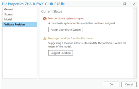
2. Click the Assign Coordinate System
Once the tool runs, the coordinate system is applied to the BIM file workspace and saved with the file for future use.
3. Click the Suggest Location
For this to work, you must have an internet connection and a map or a scene open.
4. Provide the address where the project is located.
5. Click OK.
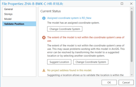
6. Click Transform to Suggested Location.
After a few moments, the Validation Position tab updates, informing you that now the model extent is within the coordinate system’s area of use and that the model is at the suggested location.
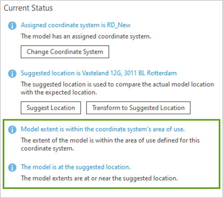
7. Click OK.
The .prj and .wld3 auxiliary files have been created.
Note: A vertical coordinate system is not defined for BIM data. If the vertical coordinate system is unknown, ArcGIS clients assume that the x-, y-, and z-units are identical. For example, if you use DHDN 3-Degree Gauss Zone 1 with meters as linear units, the assumption is that all z-values are also in meters.
Step 3: Make final positioning adjustments to the digital model
In the final step, as an example, I will show how I georeferenced a IFC file representing the high rise for the De Zalmhaven complex project in Rotterdam, Netherlands. Thank you to the Royal BAM Group (Koninklijke BAM Groep) and Esri Netherlands for making the digital model available.
Follow along with the steps or watch me work through the process in the video linked below.
Instead of adding the complete model, with its many disciplines and categories, I will only add one category for easier manipulation. I have chosen the Slabs category, which outlines the floors and is easier than others to interpret.
Note: Alternatively, the Walls category could also be used for this purpose.
1. Right-click Slabs and choose Add To Current Map.
After a few moments, the Slabs multipatch feature class appears in the scene.
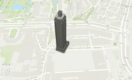
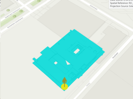
2. As expected, the building is located at the Gedempte Zalmhaven 55, 3011 BT Rotterdam, Netherlands address, which is its temporary coarse location.
Tip:
Before moving the building to its exact location, manipulate the geometry by filtering out any building floors that are not close to the ground level by using a definition query.
Now move and rotate the high-rise model to geolocate it precisely using the Georeference ribbon tab.
3. Open the Georeferencing tab. In the Contents pane, select the Slabs feature layer added to the scene.
The context ribbon for the BIM data appears.
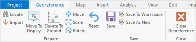
4. On the Georeference tab, in the Prepare group, click Move.
In the scene, the building activates in Move mode. Its surface becomes cyan blue and direction arrows (red, navy blue, and green) appear.
To move the feature in only one direction, hover over the specific arrow handle to be selected and drag the handle to the new position. If the feature needs to be elevated or dropped, hover over the green arrow representing Z and start moving the building in the Z direction needed (up or down).
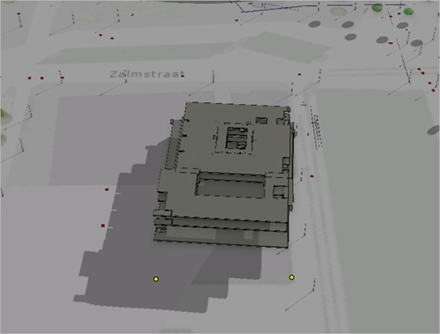
Fine-tuning the position
With the move tool active, you can relocate the anchor point by pressing and holding the Ctrl key. The icon changes to an orange cone, which you can reposition anywhere on the structure.
The anchor point can help you position more precisely by snapping to any other reference layers included in the scene, such as ground control points or the corners of known buildings.
With snapping enabled, you can position more precisely to any reference layers included in the scene.
If you know the exact angle of rotation, you can use the input window: Press A and type the degrees. The rotation is always on the horizontal plane.
The digital model is ready to use in scenes and maps in ArcGIS Pro. You can remove these test layers and add the whole model to the scene. With this building layer, you can visually inspect the various disciplines or floors. You can add more data to interactively analyze the building in the context of its environment and share the building layer, in addition to other GIS content, as a web scene .
If you would like to learn more, please see the BIM and GIS learning path.
Watch me go through these georeferencing steps in this video

Commenting is not enabled for this article.