As cities grow and change, planners need a clear way to explore future neighborhood scenarios while accounting for already approved projects.
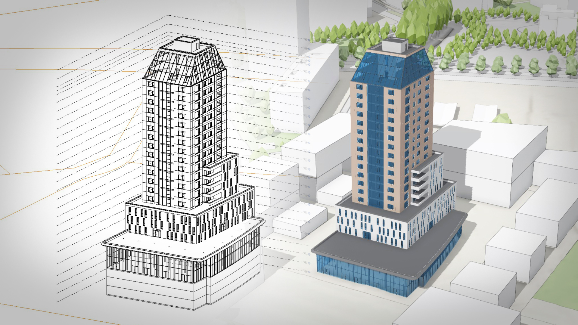
But here’s the catch: approved projects are typically delivered as detailed building models created with BIM software, like Revit.
For planners, these large files are difficult to store and share for collaboration, and nearly impossible to visualize at a neighborhood or city scale, making it hard for them to get the big-picture overview needed to make informed decisions.
ArcGIS Urban supports every stage of the planning process—from early massing volumes to detailed architectural models—bringing the digital twin concept closer to reality.
With ArcGIS Urban’s project editor, you can create more detailed buildings and outdoor spaces, as well as upload and place 3D building models in context with the built environment.
The underlying technology (a 3D object layer) supports a range of common 3D formats, such as OBJ, DWG and IFC. Quite often, IFC is the format of choice because it’s the standard for BIM exchange in the architecture, engineering, and construction (AEC) industry.
This article explains how to simplify BIM models and export them as smaller IFC models from Revit so they can be uploaded to ArcGIS Urban for a comprehensive overview of all development and planning activities in one place.
The article focuses on a specific process in Revit, but similar workflows apply to other BIM platforms.
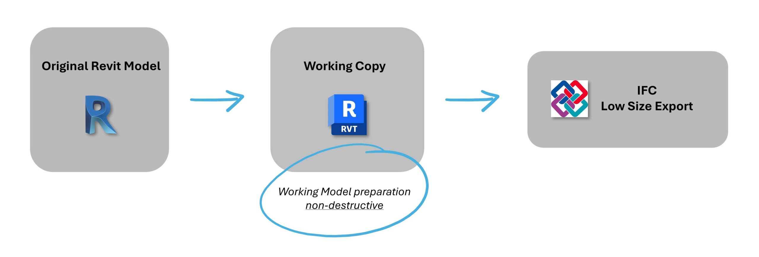
A nondestructive workflow
To get rid of unnecessary geometry and information in the exported file, we’ll apply a nondestructive workflow, going through the following steps in Revit:
- Set up a view and a view template: “what we see is what we export”
- Set up a project base point: to specify the model’s insertion point in Urban
- Set up an IFC export: configuration settings for a lightweight IFC model
Keep in mind:
This workflow is applicable to models that use a single Revit file.
If your Revit project uses multiple files for different disciplines—such as architectural, structural, or MEP—adjusting the project base point may affect the alignment between models.
To prevent this issue, always prepare the Revit model for ArcGIS Urban in a separate working copy.
Set up a view and a view template in Revit
The first thing to be aware of while using this method is that only visible building elements will be exported to the IFC file.
In other words, “what we see is what we export.”
For this reason, we must avoid exporting from a 2D view like a plan sheet or section—which only shows a reduced part of the project—and do it from a 3D view.
Create a 3D view
The easiest way to create a new 3D view is by duplicating an existing default 3D view.
As shown in the animation below, we can easily open a default 3D view, duplicate it, and rename it from the Project Browser:
In the properties panel, we can manage many attributes of the 3D view, but the important thing for us is to configure a customized view template.
Create and assign a view template
We can easily create a new view template from the current 3D view, as described in the animation below.
Next, we must assign the view template to the 3D view.
We can access the “Assign View Template” window from the properties panel, then pick our new view template from the list, as shown in the clip below.
Now, all the visibility/graphic overrides of this 3D view are driven by the settings of the assigned view template.
This means they can’t be directly managed from the properties panel (they will show grayed out) and must be configured from the “Assign View Template” window.
Configure the view template
Now, the actual configuration work starts.
Visibility/Graphic overrides model
Edit “Visibility/Graphic Overrides Model” and navigate through the model categories to uncheck the visibility for those we don’t want and therefore won’t be exported later.
Here, we may hide all categories that don’t affect the exterior appearance of the building, like “HVAC,” “Furniture,” “Casework,” etc.
Note: Ensure the origin coordinates in the “Site” category remain checked. This visibility is necessary for adjusting the model’s insertion point later.
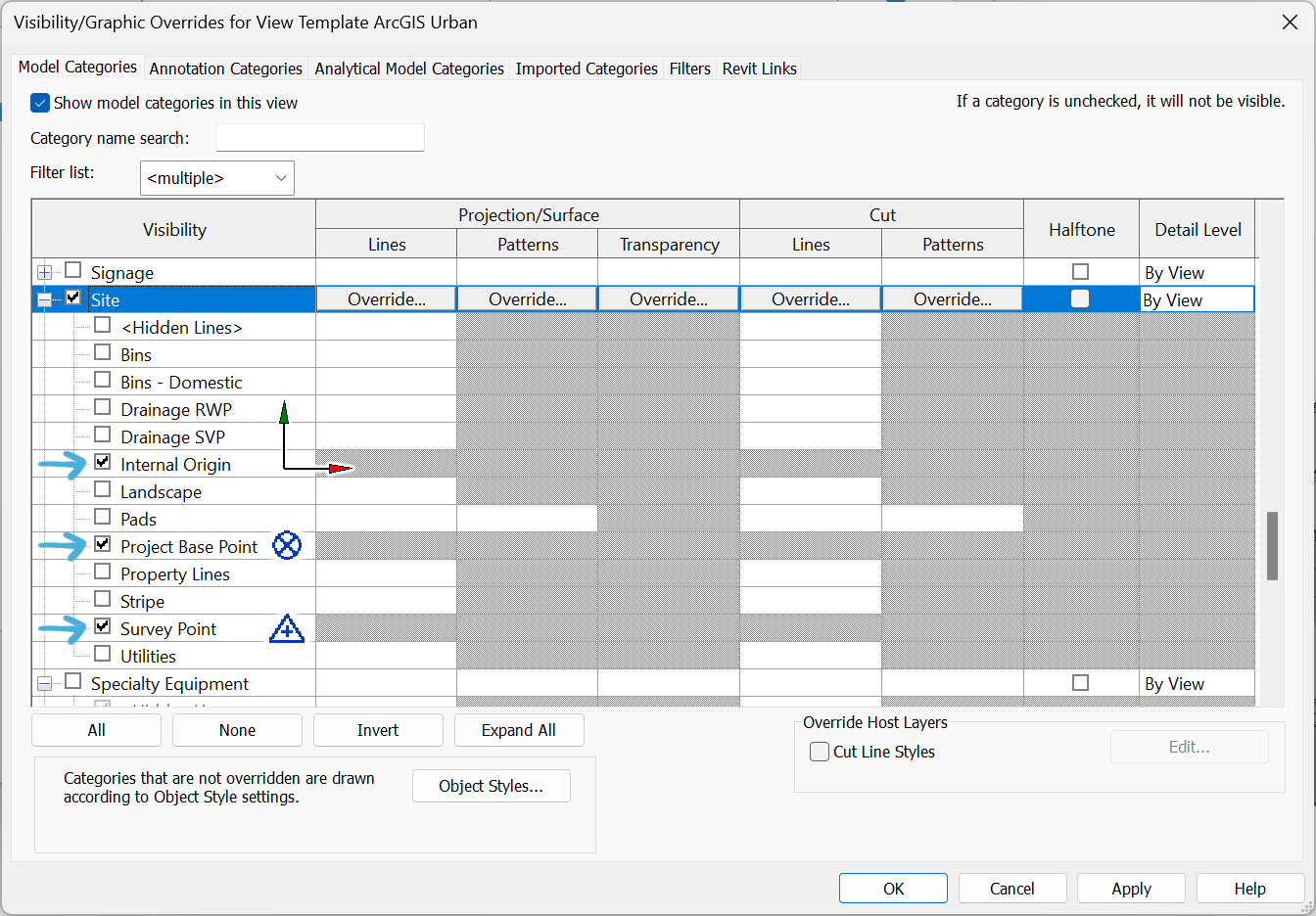
Other category groups—such as Annotation Categories, Analytical Model Categories or Imported Categories—can be excluded completely, unless we have a reason to leave them visible.
Keep in mind:
Since this approach is based on category visibility, it will only be effective if our model has been properly modeled in Revit with elements created in their corresponding categories.
Detail Level
The Detail Level of the families can be set to Fine, Medium, or Coarse.
The outcome of this setting really depends on the families used in the project. In some cases, the amount of geometry can vary drastically from one setting to another, while for other families, there are little to no changes at all.
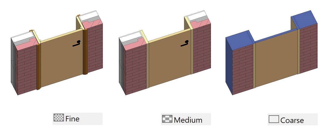
In general, the Fine setting is not recommended because it will result in heavier models.
Obviously, the Coarse setting will result in lighter models, but we should make sure that nothing important disappears when using this setting (see image below).
If we’re not sure about the outcome, we recommend using Medium, and only using Coarse if we’re certain that no important parts of the model will be omitted.
Model Display
Since IFC does not support textures, we recommend setting the Model Display style to “Shaded” to match the appearance of the IFC model being exported.
Other settings
In case your BIM model has parts or phases, make sure “Parts Visibility” and “Phase Filter” are set to the option you want to export.
Other settings like shadows or rendering settings are not relevant to the exported model.
Keep in mind:
It is always possible to hide individual elements by right-clicking on them and selecting “Hide in View.”
Although this option might be useful in some cases, like elements in the “Generic Model” category, it makes it difficult to keep track of all hidden elements.
Therefore, managing visibility by category as explained above is preferred as a general workflow.
Set up project base point in Revit
We can utilize the Move tool in Revit to position the project Base Point. This point in the Revit model should correspond to the insertion point in ArcGIS Urban.
There are basically three approaches to position our model:
1. Approximate location
If we aim to roughly place the model in Urban, it doesn’t matter whether our Revit project is geolocated.
A good practice in this case is to place the project base point at a recognizable part of the building—for example, a corner on the ground floor.
This way, we can use the manual transformation tools in Urban to move and rotate the model to the desired position.
Note that this point will serve as the center of rotation in Urban, so it is advisable to choose its location carefully.
2. Precise location using snapping
If our Revit model is properly placed within its parcel—but not necessarily geolocated—we can place it at its actual location in Urban using a clearly defined point, like a parcel corner. This point will need to be set as “Project Base Point” in Revit.
For this method, coordinates are not necessary, but the “Angle to True North” must be correct for the building to be properly oriented.

Since Urban provides its own parcel layer, we can insert our building snapping directly to the same corner of the parcel.
Note: As the parcel in Urban is projected onto the terrain, the elevation (Z) of the insertion point equals the height of the terrain at that point. Hence, the model might need to be shifted upwards or downwards.
3. Precise location using coordinates
If our model was properly geolocated in Revit, we can place it at its exact location in Urban.
There are two options of positioning our IFC model using coordinates:
3.1 Entering the coordinates manually
This option is valid for any version of the IFC schema.
In this case, we should set our project base point at a specific point in the project whose coordinates are known, like a parcel vertex or an existing survey point.
It doesn’t matter if the project base point is not a defined point in Urban; we can type its coordinates directly in the “locate” dialog while placing the model.
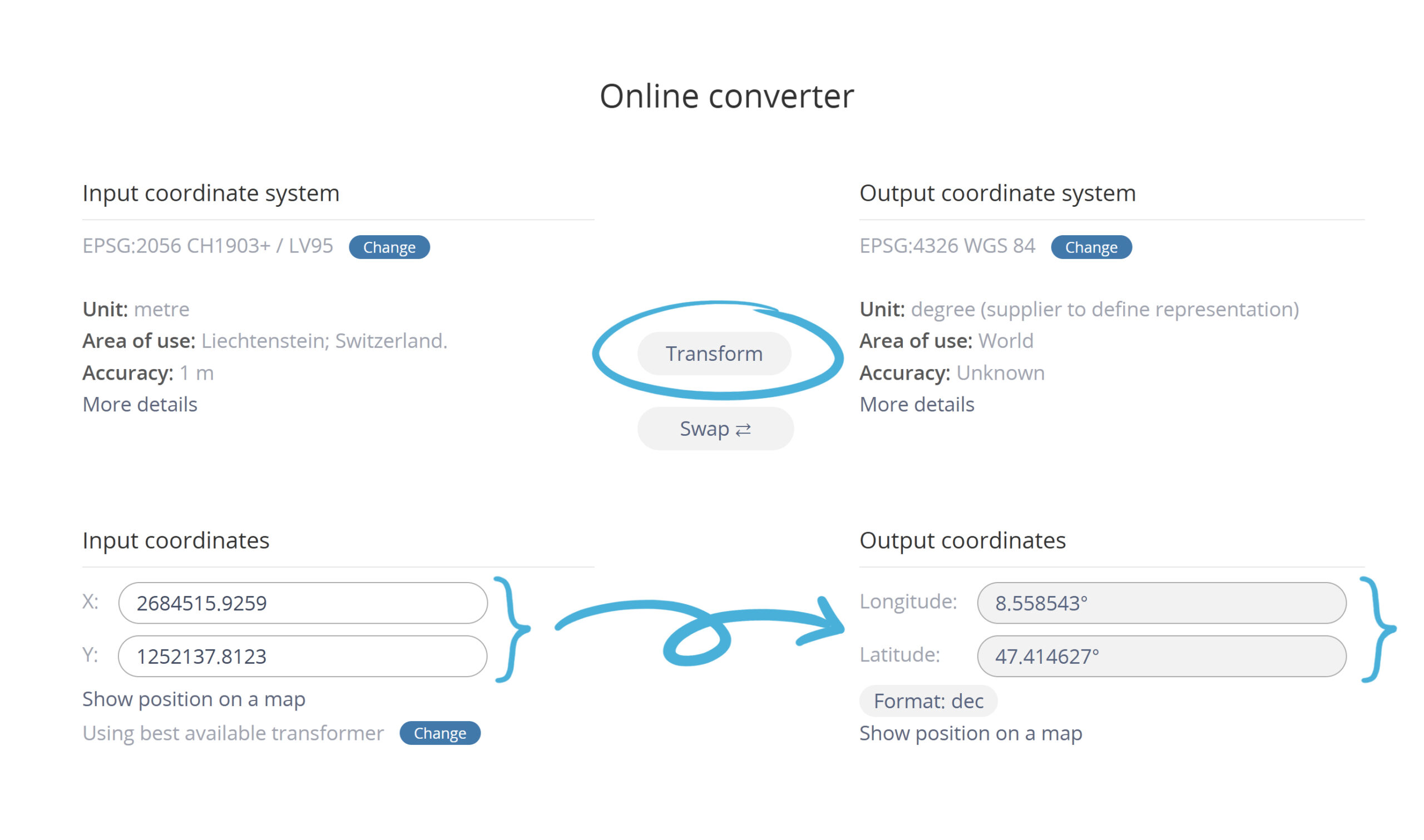
Depending on the coordinate systems we’re using in Revit and Urban, the coordinates should be converted using a tool like EPSG.io.
See “Brief note about coordinate systems” below to understand how coordinates work.

Keep in mind:
Ensure that the input coordinates in the converter tool use the correct units.
In this example, Revit coordinates are in centimeters, while EPSG.io uses meters for that coordinate system. Adjust the units accordingly, especially when copying and pasting coordinates.
3.2 Automatic location
This option is only valid for IFC4 and later versions of the schema.
If the uploaded IFC model is georeferenced, it will automatically be placed at the right position.
See section below “IFC export settings in Revit—Geographic reference” for the correct Revit IFC export setup.
If you want to learn more about automated location of 3D models that contain georeferencing information, you can check out the article 3D Object Layer: Upload Georeferenced 3D Models.
Brief note about coordinate systems
Coordinates in Revit are usually defined in a projected coordinate system, like a country-specific coordinate system.
In ArcGIS Urban, we can work with geographic or projected coordinate systems.
The coordinate system used depends on the selected basemap when we setup the Urban model for the first time and cannot be changed later.
To learn more about how coordinate systems work in Urban, you can visit this section of the ArcGIS Urban documentation.
Ideally, for the most accurate location of the model, Revit and Urban should use the same projected coordinate system.
If that is not possible, we must transform the Revit coordinates to enter them in Urban using a transformation tool like EPSG.io, as shown in the example above.
Keep in mind that geographic to projected coordinates transformations always involve a certain divergence. Therefore, a difference of some centimeters is expected.
See viewing modes to learn about the technical differences between local and global scenes, and supported coordinate systems for further information.
IFC export settings in Revit
After making sure the current Revit view is set to the 3D view we configured above, we may start setting up the export to IFC.
Modify export setup
An extensive description of every setting is beyond the scope of this article. Instead, the animation below serves as a quick guide for configuring a typical low file size export setup.
Below, we will discuss the most relevant settings for each tab.
General:
The recommended IFC version is 2×3 or higher.
Using IFC4 or newer ensures that the exported model includes geographic location coordinates.
Newer IFC versions, such as 4 or 4×3, generally produce smaller file sizes.
Additional content:
Select “Export only elements visible in view” to limit the export to what is displayed in the current 3D view.
Enable “Export rooms, areas, and spaces from 3D views” if this BIM information is essential for the model’s purpose.
Note that Urban does not currently access this data, but future updates will include this capability.
Property sets:
Property sets are not necessary for ArcGIS Urban projects that focus on 3D geometry.
However, a model without IFC property sets does not fully qualify as a BIM model. Therefore, it is advisable to export IFC common property sets.
If file size is a concern, unchecking the export of these property sets can reduce the size by about 20 percent without affecting the geometry.
While this approach is totally acceptable for exporting models to Urban, it’s important to note that the resulting model will be a 3D model rather than a true BIM model.
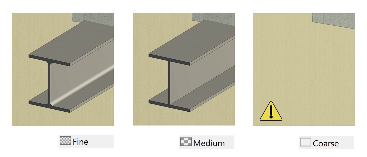
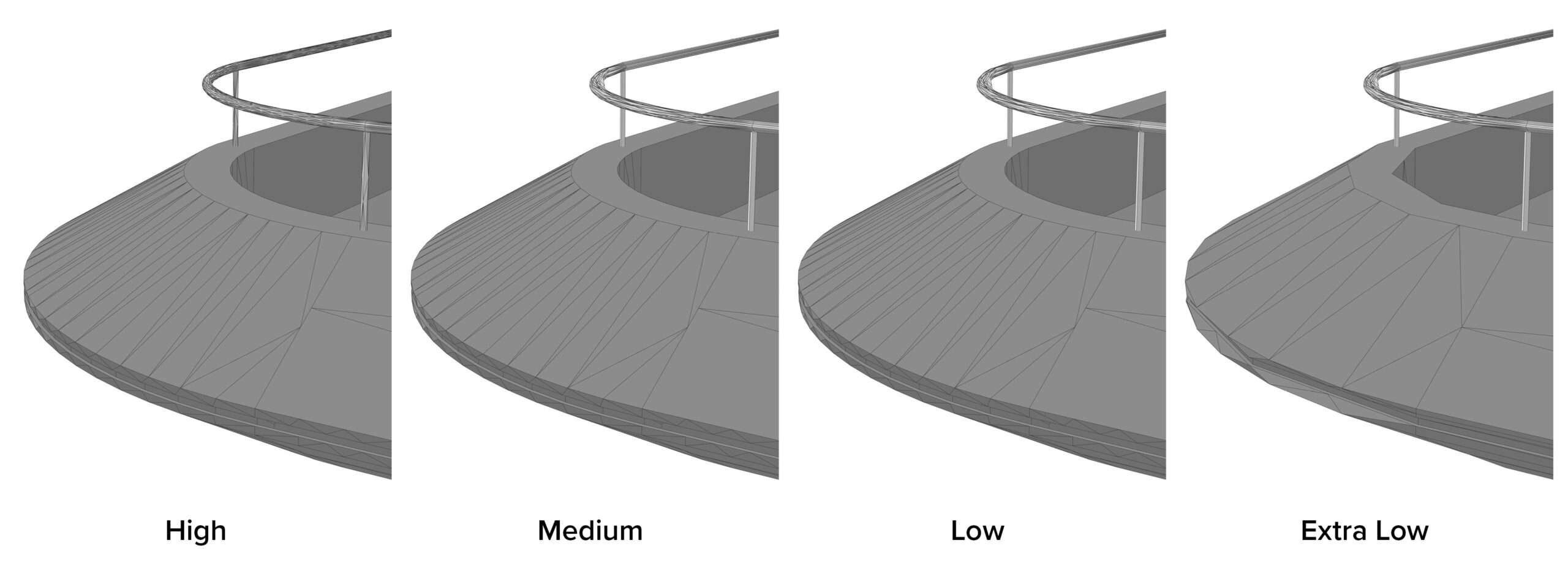
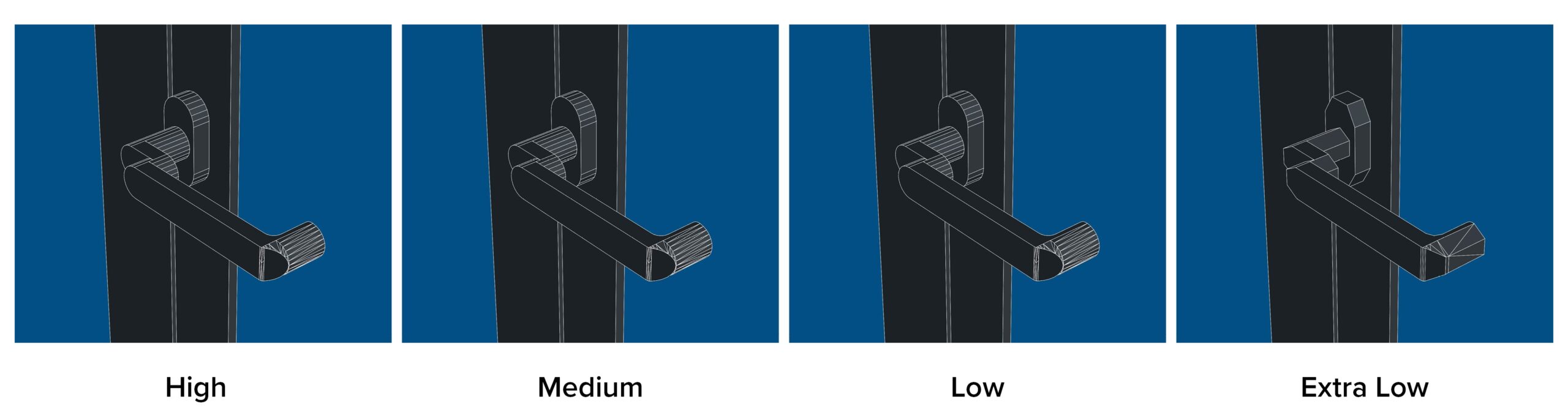
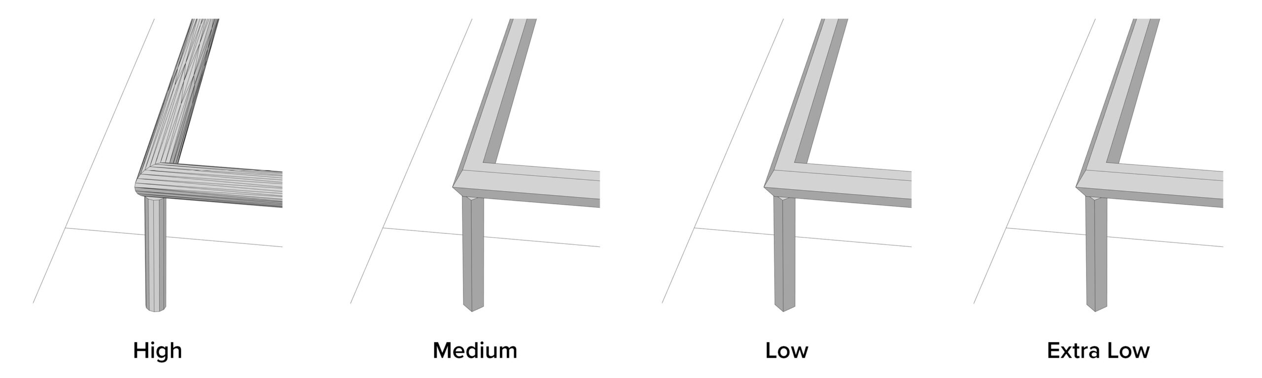
Level of detail:
We can choose from four levels of detail: High, Medium, Low, and Extra Low.
This setting affects the polygon count of some element geometries.
As shown in the examples below, the results may vary depending on the element.
Advanced:
Ensure that the “Use active view when creating geometry” option is checked. This will export only visible elements in your current view.
Geographic reference:
This information is only relevant if we aim to precisely position our model using coordinates, which is only available for IFC4 or higher.
Set the “Coordinate Base” to “Project Base Point” or “Project Base Point Oriented in True North” to ensure the exported IFC has its coordinate origin in the correct location, as described earlier.
Setting the “Coordinate Base” to “Project Base Point Oriented in True North” ensures the correct orientation of the model when using the automatic location method described above.
Setting the “Coordinate Base” to “Project Base Point” will require entering the orientation angle manually in Urban.
Automatic geolocation of the model is supported by ArcGIS Urban only when the Revit model and Urban share the same projected coordinate system (EPSG code).
The “Projected Coordinate System Reference” data shows the corresponding coordinates, elevation and angle from True North as configured in the Revit project.
However, since Revit doesn’t directly store projected Coordinate Reference Systems (CRS), the EPSG code must be entered manually by the user for the exported IFC to be properly geolocated.
Lastly, we can save the export setup configuration as a JSON file, which can be reused for other models if needed.
Summary
We hope this article has provided you with valuable insights on how to effectively export IFC models for seamless import into ArcGIS Urban.
Remember that each new release brings exciting features, so be sure to stay updated on the latest enhancements!
Let us know if you have any feedback or questions by connecting with us on the ArcGIS Urban Esri Community page.


Article Discussion: