In our previous articles, we have shown how you can use the Electric Utility Network Foundation to create subnetworks along with how to manage and validate subnetworks in a variety of different scenarios. You can find all these articles, and more, in the Learn ArcGIS Utility Network for Electric learn series. We showed how updating your subnetworks plays an important role in reporting and quality assurance. In this article, we will show additional tools and techniques you can use in your quality assurance workflows to identify and correct problems with your data.
Before we discuss these new techniques, we should quickly define what quality assurance means within the context of GIS. All utility companies have some form of quality assurance, whether it’s a foreman overseeing new construction, a field worker performing preventative maintenance, or a GIS technician making map corrections. All these activities are considered quality assurance because they are examples of a process put in place to ensure that an asset satisfies the operational requirements of the utility.
This brings us back to how our tools and processes with the utility network are incorporated into the quality assurance workflows for the GIS department as a utility company. The following diagram shows the tools and workflow associated with editing data in a versioned, enterprise geodatabase with a utility network and attribute rules.
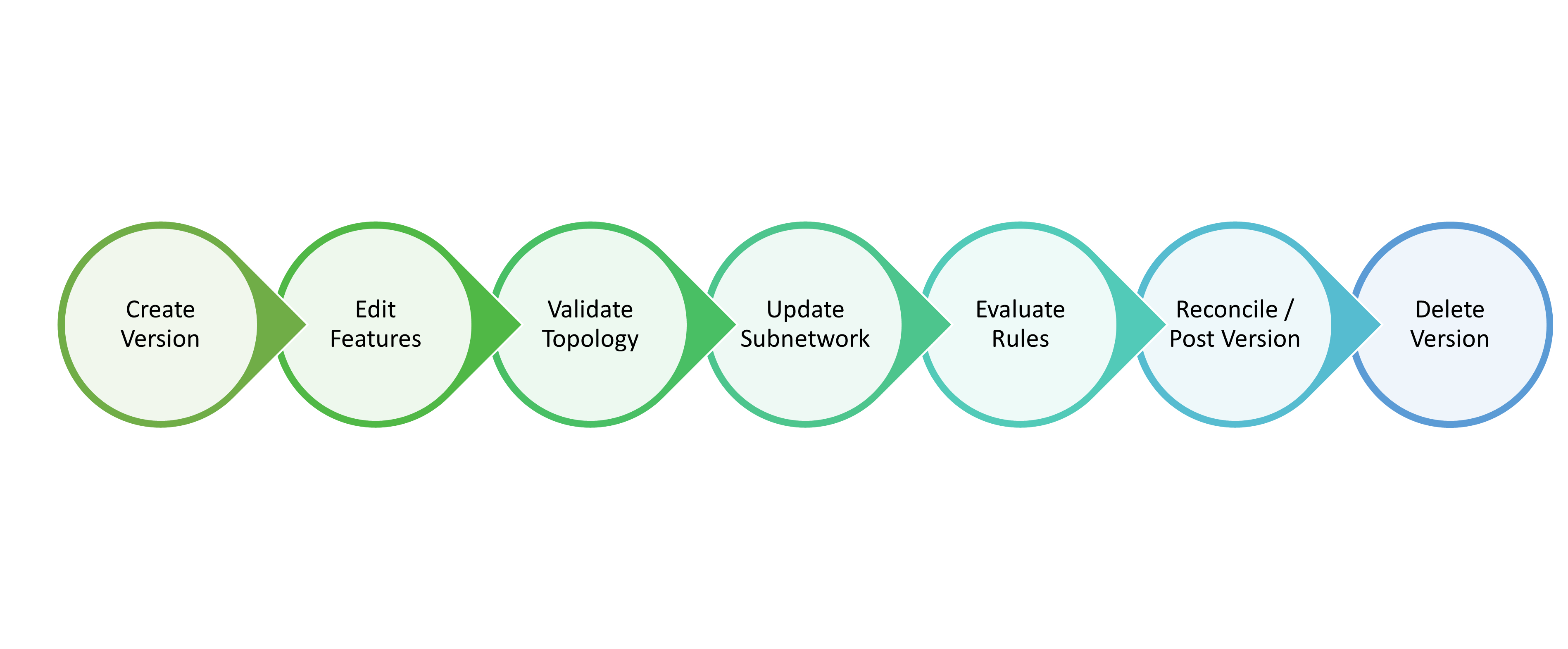
At every step of this process the GIS is helping the editor improve data quality, below are just a few examples:
Edit Features – The editing environment in ArcGIS Pro prevents editors from creating bad data by providing picklists, preventing users from creating invalid relationships/associations, and enforcing connectivity rules with snapping.
Validate Topology – The validate topology command will ensure that the edited data meets all the constraints and rules defined for the utility network. You can learn more in the online help or by reading this blog specific to electric networks.
Update Subnetwork – The update subnetwork command will ensure that all the features in a subnetwork meet the constraints and rules defined for the subnetwork being analyzed. You can learn more in the online help or by reading this blog specific to electric networks.
Evaluate Rules – Attribute rules allow you to programmatically edit and validate data to enforce your business rules. They also allow you to use the error inspector to review and create exceptions for any issues encountered. You can learn more about managing attribute rule errors using the error inspector in the online help.
Reconcile – This step will update your version with all the edits that have been made to default since you created your version or last reconciled and it will determine if any of the edits made in your version conflict with edits made to default. Regularly reconciling versions should be considered a key piece of the quality assurance process since it ensures that editors are always working on the most current data and ensures that conflicts are identified and resolved while those involved in the work/edits are still engaged.
The quality assurance processes outlined in this blog typically occur during the evaluate rules step because they are usually performed by a specially trained user who is familiar with both the tools and business requirements that are required to identify and resolve any issues identified during these checks.
Quality Assurance Checks
Now that we’ve discussed which parts of your workflow are best suited to perform quality assurance, let’s discuss what these checks look like in more detail.
Below you will find a summary of the most common issues and resolutions that electric customers implement in their utility network that aren’t already covered by topology errors or subnetwork errors.
| Issue | Description | Resolutions |
| Inconsistent Subnetwork Name | Inconsistent subnetwork name on a subset of feature in the network. | 1. If the affected feature is allowed to participate in multiple parent subnetworks, then this is not an issue.
2. If the affected feature should only participate in a single-parent subnetwork, then you will need to determine which system it belongs to and isolate it from the second system. |
| Unknown Subnetwork | Features that should be energized that do not belong to a subnetwork. | 1. If the affected feature is not active or does not need to participate in a subnetwork, then this is not an issue.
2. If the affected feature should participate in a subnetwork, then you should review the condition barriers and propagators associated with your subnetwork to determine why the subnetwork was unable to reach the feature. |
| Loops | Features in a subnetwork that have indeterminate flow. | 1. If the affected area is looped in the field, then this is not an issue.
2. Review the area to identify and correct the location where the loop should be broken. |
| Underserved | Features in a subnetwork with one or more de-energized phase. | 1. If in the field not all the phases of the feature are energized, then this is not an issue.
2. If all the phases on the feature should be energized, then you should look at the path between the feature and its controller to identify and correct the location where phasing has been restricted. |
Let’s now look at several real-world examples that display each of these issues and the tools we will use to identify and resolve them.
Inconsistent Subnetwork Name
When a feature belongs to more than one subnetwork, we say that it has an inconsistent subnetwork. Inconsistent subnetwork connectivity is usually identified by the update subnetwork operation, which will create an error when two or more subnetwork controllers with different subnetwork names are traversable to each other. There are several scenarios where this type of traversability is allowed by the software, and we allow a feature to participate in multiple subnetworks without creating an error. The following situations are when we allow features to belong to multiple subnetworks:
Structures Features – Structures and assemblies are allowed to contain or have attachments with features from multiple subnetworks.
Tie Device – When a feature such as an open switch acts as a barrier between two subnetworks it is connected to both networks.
Subnetwork Controller – When a subnetwork controller is energized by another subnetwork it is connected to both networks, acting as a barrier to the first and a source for the latter.
Isolated Area – Because there is equipment in the electric network that only allows power to flow in one direction, it is possible to create small areas in your subnetwork that are fed by multiple subnetworks without the subnetworks controllers themselves becoming connected.
Identifying Issues
When looking for inconsistent subnetworks you are typically looking for the situations where an isolated area of the network belongs to two subnetworks, since most electrical networks aren’t designed to operate this way. You can identify these features by looking for electric features that have multiple subnetwork names concatenated in their subnetwork name field.
The easiest way to do this is to create a layer for each of your electrical classes and apply the following definition query:
Electric Junction/Electric Line/Electric Edge Object: SUBNETWORKNAME LIKE ‘%::%’
Electric Device / Electric Junction Object
In the case of electric devices, you will need to filter out any devices that are barriers or subnetwork controllers
SUBNETWORKNAME LIKE ‘%::%’ AND CURRENTDEVICESTATUS IN (Null, 0,2) AND ISSUBNETWORKCONTROLLER = 0
This query will identify all features that belong to multiple subnetworks, are not acting as a barrier feature, and are not a subnetwork controller.
Once you’ve created this layer you can now visually identify features with this issue on the map as well as through review of the attribute table for the layer.
Verify correctness
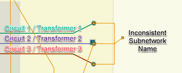
One situation where an inconsistent subnetwork may be considered acceptable is in scenarios where you have created a spot network with multiple transformers from different subnetworks. In these situations, it is considered best practice to create a new low voltage subnetwork for the transformers; however, if you don’t have a business process for naming spot networks you can leave the issue uncorrected in the short term. Below you can see an example of a spot network with three transformers fed by three separate subnetworks.
The consequence of leaving this issue uncorrected is that any time a trace is run on any of the affected subnetworks they will include all the features in the inconsistent subnetwork area. If you have an interface between your utility network data and other network analysis tools (OMS, Engineering Analysis, etc.) this may result in duplicate features or other problems with this area in those external systems.
Separate the subnetworks
Another common cause of inconsistent subnetworks are scenarios where a customer has inadvertently connected to multiple transformers on different subnetworks. In the example below you can see a change between the original design and the final as-built has resulted in the customer being connected to transformers on different circuits.
To resolve the issue, we would update the GIS to match the as-builts for the job. If a significant amount of time has passed between completion of construction and the issue being discovered, you should also consider having this information field verified. Below you can see what the GIS looks like after making updates based on a field check.
Unknown Subnetwork
The next issue that utilities often look for is features that are de-energized, or in terms of the utility network, features that have an unknown subnetwork. These features can be identified by looking for a subnetwork name attribute with the value ‘Unknown’.
When reviewing these types of issues, it’s important to consider the following exceptions to this rule:
- Supporting Features – Depending on your business requirements not all features need to be part of a subnetwork. It is quite common for some types of equipment or structures to be exempt from this requirement: examples include down guys, neutral wire, and grounding equipment.
- Proposed Construction – Because new construction isn’t energized yet it is typically not required to have its subnetwork name populated. However, most utilities have processes in place in their design tools or GIS that will help them analyze proposed construction as part of their proposed circuits. You can find examples of some of these processes in this blog.
- Abandoned Features – Abandoned features should not participate in or support any subnetworks.
Identifying Issues
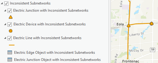
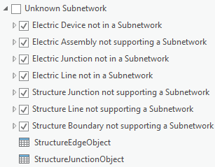
Looking for features that belong to an unknown subnetwork can be achieved using several different techniques. While you can review the attributes of individual features, the Electric Data Audit display in the Electric Utility Network Foundation includes a series of layers with definition queries that can be used to highlight features with issues.
These definition queries take into account the conditions described above like asset group and lifecycle status and that fact that structures and electric features use different fields to represent their membership in a subnetwork. If you have added any additional asset groups to your model or use a different set of lifecycle statuses, you may need to adjust the definition queries. Below are the definition queries used by the electric device and structure junction layers:
Electric Device
SUBNETWORKNAME = ‘Unknown’ And ASSETGROUP <> 1 And lifecyclestatus IN (2, 6, 4, 3)
Structure Junction
SUBNETWORKNAME = ‘Unknown’ And ASSOCIATIONSTATUS = 2 And lifecyclestatus IN (2, 6, 4, 3)
In order for these definition queries to work effectively you should ensure that the subnetwork name attribute has been updated for all the features in your area of interest. If you are in the default version than you just need to make sure that you have updated all the subnetworks in the area. If you are in a named version, then only new features or features modified in your version will have their subnetwork name populated. This means when relying on the definition queries to identify features with an unknown subnetwork in a version, you should always double check the results by running a trace, in-case the features were not edited in your version but have been fixed.
Verify correctness
One common situation where features will be intentionally de-energized is known as a “dead span”. This is when a span of conductor between two structures, typically two poles, is kept de-energized but can be used back feed or restore power during an outage. Below you can see an example of a dead span between two poles, note that there are open points on either end of this conductor to represents the location where a crew can place a jumper in the field to energize the conductor.
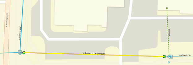
It is also possible, but less common, to find intentionally de-energized spans of conductor in underground systems when the elbows on either end of the conductor are kept open. These de-energized sections still behave in a similar fashion to their overhead counterparts, with open devices on either end of the section and no de-energized devices in the area.
If you have a need to extract and model de-energized features in your OMS or ADMS you can find more information about the configuration and workflow supporting that behavior in this blog.
Identify path to source
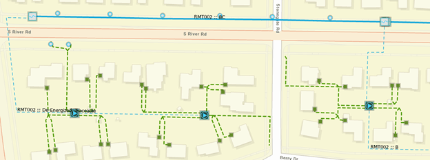
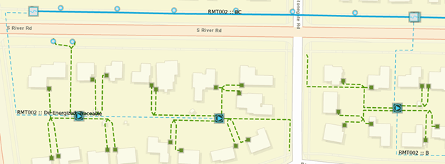
It is very uncommon for an in-service device to not belong to a circuit in the field. When you identify the equivalent of this in your GIS, a device with an unknown subnetwork, you should take time to investigate and correct the issue. In the following example we can see an area with many features that have an unknown subnetwork.
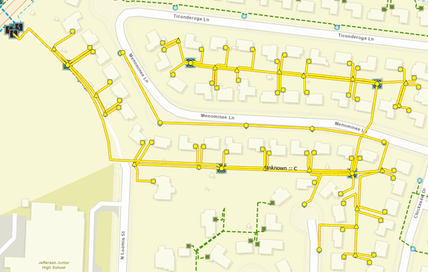
You can see that all the features are connected to a single location on the west side of the map. If you zoom in, you can see this is a switch cabinet with one switch and three fuses. I have annotated the graphic below to show how electricity is flowing from the circuit breaker.
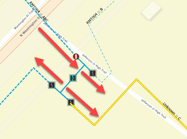
This type of switchgear is commonly used to isolate and protect an area of the network. The switch on the upstream side can be opened to isolate the area. Each of the downstream sections of the network are connected to a fuse, that will trip open in case of a fault and isolate the outage to the affected downstream area.
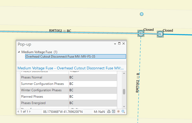
If we investigate the fuse bank associated with our de-energized section, we can see that all the fuses are marked as open, indicating this area is intentionally de-energized in the GIS.
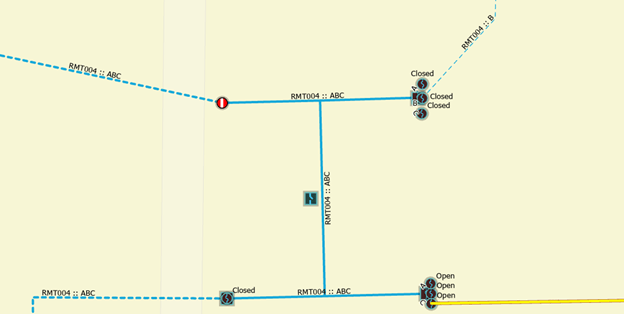
Because there are customers receiving power in the area that the GIS is showing as de-energized, we know that a data quality issue is present which needs to be corrected. After reviewing the area with someone in operations they confirm that there was an outage recently in the area, and even though they were tripped during the outage they are currently and normally closed in the field. We can now confidently update the GIS with the correct position, update the subnetwork, and see that our section of the network is once again energized!
Loops
Loops are areas in a subnetwork with an indeterminate flow. This happens when an electrical trace discovers power flowing in opposing directions in an area. This has the effect of causing upstream and downstream traces that pass through a looped area to return all features within the loop.
Loops are expected in mesh networks because there are multiple sources, and therefore most features will have multiple sources of electricity. In contrast, most radial networks are designed so that every feature in the network only has a single path back to its source.
Identifying Issues
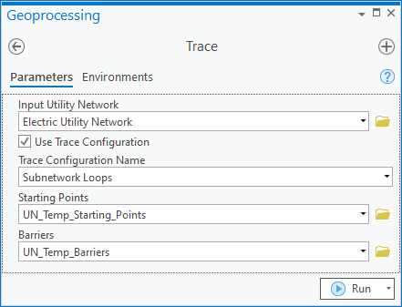
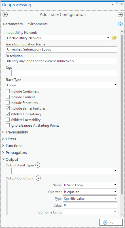
One of the most effective ways to identify loops is to use the Loops trace. The loop trace will identify all the features in an area that have indeterminate flow. This trace requires that you provide a set of condition barriers to limit the analysis.
Because this trace is typically performed at a subnetwork level, you should create a named trace configuration with the correct settings that can be re-used.
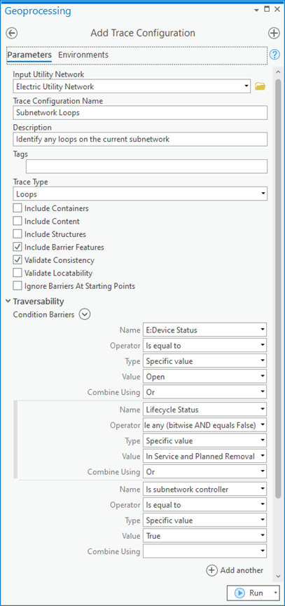
Once you’ve created a named trace configuration for this purpose, anyone can reuse that configuration to identify loops within a subnetwork.
Because this check is often associated with subnetworks you should consider checking for loops on dirty subnetworks before running update subnetwork so you can be confident that the clean subnetworks are loop free.
Verify correctness
While most utilities avoid maintaining loops in their network, there are times when an area is intentionally built to be looped.
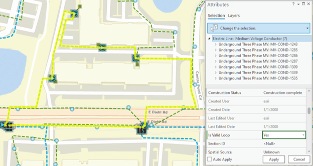
If after researching a looped area in the GIS you have been told by operations and engineering that the loop is intentional and can be safely ignored, then you should update the GIS to reflect this. The model contains a field called “Is Valid Loop” that you can use to indicate when a loop is intentionally built in the system. To do this you would select all the features in the loop and populate the field to be Yes (stored as 1 in the database). This field doesn’t affect the loop trace or the network, but it does allow you to quickly verify that certain looped features can be safely ignored.
If you find you have many intentional loops in your system you may want to create a second named trace configuration for loops that will ignore verified loops. To do this you would use the same trace configuration created in the previous section, but you would add an output filter to only show features where the Is Valid Loop field is set to No (stored as 0 in the database).
If we look for loops using the new named trace configuration, we can see that the Valid Loop we identified earlier is no longer being returned.
Break the loop
Underground residential construction is often built so that any given location can be potentially fed from either direction. What keeps this from being looped is the placement of elbows in the open position for key pieces of equipment. When maintenance occurs, the elbows can be opened and closed, as appropriate, to isolate the affected area and keep as many customers in service as possible.
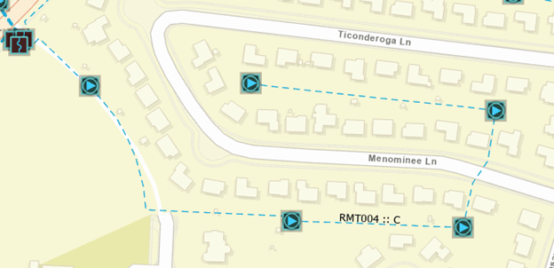
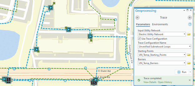
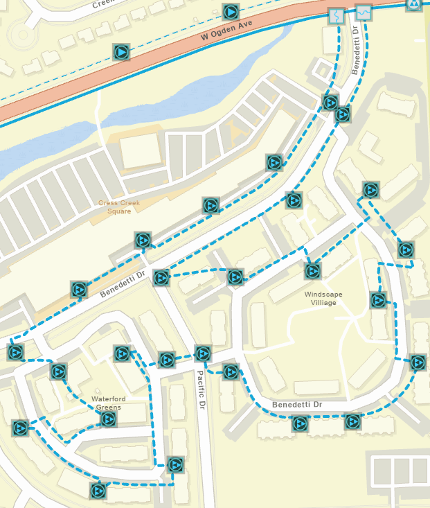
Because the open elbow(s) in these looped areas can periodically change, the GIS can get out of sync with the field at times. In the screenshot below we have run a loop trace on this subnetwork and found that one of our neighborhoods has become looped.
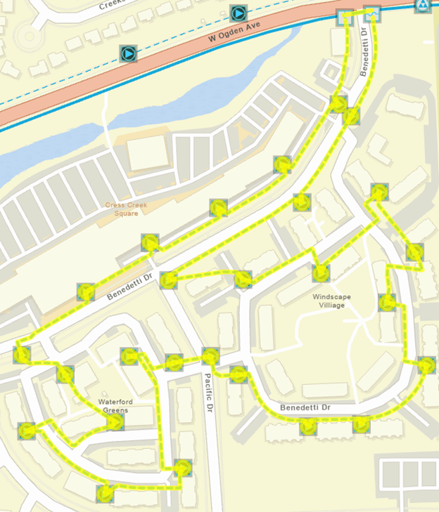
The open point in this loop could be at any of the transformers in the area. To determine which transformer elbow is open you would want to discuss this with a system operator to determine the current state of the network in the field. If there was any uncertainty about which elbow it was, you would likely need to dispatch a field crew to verify the status of equipment in the area. In our case the field crew reports back that the street side elbow on the transformer at the corner of Benedetti Dr. and Pacific Dr. is open, and you can update the elbows in the GIS to reflect this.
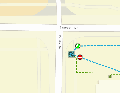
Next, you run validate topology in the area to ensure the features were correctly edited and then rerun our loop trace. You will see that the features in this area are no longer selected, which means the area is no longer looped.
Underserved
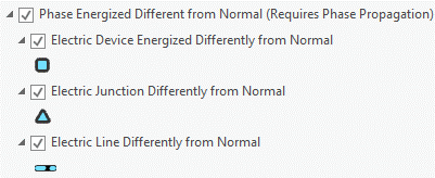
This issue is only applicable if you have configured and maintain phase propagation for your electric networks. If you are unfamiliar with attribute propagation, you can learn more about it in this blog. When using phase propagation there are three fields used to represent phase in the data model:
Phase Change – This is the field used to control phase propagation in the model. It only needs to be populated on features that control or change phasing in the model. Common examples include network sources and single-phase devices.
Normal Phases – This is the expected phasing for the device, line, or junction in the network that managed by GIS editors. It is used to compare against the energized phases to determine whether the feature is properly energized in the utility network model.
Energized Phases – This is the phasing that calculated by the utility network by the update subnetwork command.
Something is considered underserved when the energized phases of the feature do not match the expected normal phases of the feature in the GIS. In addition to this being an indicator of data quality issues with the affected features it can also lead to additional issues if there are features downstream of the underserved area that relied on the missing phase(s).
Identifying Issues
As stated above, underserved features can be identified by a mismatch between their energized and normal phases. The energized phases field is populated when you run update subnetwork, so it’s important that before you spend any time investigating these errors that you confirm that their subnetwork is clean.
Because this check can be represented as an attribute query, it is most often performed by creating a layer with a definition query. You can find an example of this in the Electric Data Audit display in the Electric Utility Network Foundation solution.
The definition query on these layers will identify all the features that have a normal phase that indicates they are energized, a propagated phasing that indicates they are energized, and the two fields do not agree on which phases are energized.
Verify correctness
The most common situation where this is considered acceptable is when there is a device or line in the field that deliberately has one or more phases de-energized. The process for verifying correctness is similar to verifying correctness for features with an unknown subnetwork. You should verify the configuration of the area in question with someone who is familiar with how it is configured in the field to confirm whether there is in service, de-energized equipment.
A common example of this is when an area that was three-phase has been reconfigured to be single-phase, but the extra equipment has not been removed. You can see an example of this below.
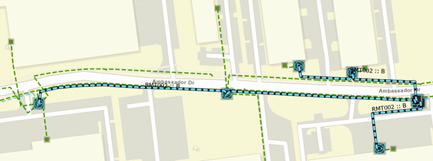
Because the area is underground, we decided to keep the three-phase conductor in the ground because it would have been too expensive and disruptive to remove the old unused conductor. Once you have confirmed that the GIS is correct, the features can be safely ignored but make note of them for future checks.
Verify path upstream
The most common cause of underserved features is when a feature upstream is drawn or attributed incorrectly. This can be as simple as drawing a single-phase device in-line with a three-phase line, incorrectly attributing a three-phase device to have less phases, or inadvertently opening the wrong phase on a three-phase device.
In the image below you can see an area that is underserved.
To identify the problem, we look at the most upstream location that is showing the issue. You can see that the problem originates immediately after one of our fuses. When we review the fuse the phasing of this fuse is set to BC instead of ABC.
After setting the phase of the fuse to the correct value, ABC, note that the phasing issues on the downstream features have been corrected.
De-energized
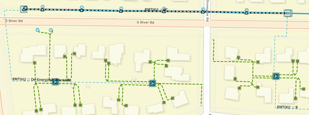
If an area isn’t receiving any phasing, any features in the area that rely on the missing phase(s) will have their energized phases set to “de-energized” and will not be assigned to a subnetwork. You can see an example of the de-energized layer in the Electric Data Audit Display below:
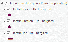
Referring back to our earlier example and turning on the de-energized features layer, you can now see that there was a single-phase line that was dependent on the missing phase in the area. Because the required phase isn’t available for these features, they have become de-energized.
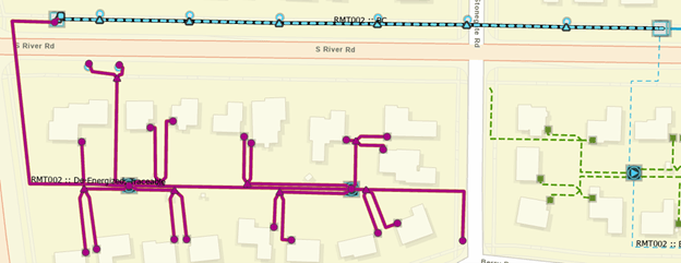
To correct the situation, apply the same fix from the previous example and correct the phasing of the first upstream fuse. After making the correction and running update subnetwork, you can see that in addition to correcting the underserved issue with the mainline features we also corrected the de-energized features on the tap.
Conclusion
Congratulations! Now that you’ve finished this blog you are well equipped to discover and fix data quality issues found in electrical utility networks. You should have a good understanding of how to make use to definition queries and the trace tool to find issues, along with a good understanding of what to do to correct these data issues.
If you’re interested in more learning content related to the utility network check out the Learn ArcGIS Utility Network for Electric learn series. You can also try these hands-on tutorials related to this article:
- Create and Manage Subnetworks
- Edit and Validate Subnetworks
- Perform Quality Assurance on Subnetworks
If you don’t have your own dataset to test these workflows, I recommend you explore the Electric Utility Network Foundation solution provided by the ArcGIS Solutions team. This solution contains sample data and maps you can use to explore and learn with the utility network!
This is the last blog in the Managing Electric Networks blog as well as the final blog in the Utility Network Error Management series. You can find a list of all the blogs in this series here Keep your eyes open for upcoming blogs from the team next year. We are actively working on new series addressing best practices, configuration, and some of the unique workflows surrounding the utility network. In the meantime, please check out the Utility Network community page on the Esri Community site. You can use this space to connect with others who are interested in the utility network, ask any questions you have about the utility network, or even share your own experiences with others!


Commenting is not enabled for this article.