In our previous article, we discussed how subnetworks in the utility network are configured using the Electric Utility Network Foundation. In this article, we are going to dig into what happens behind the scenes when you update a subnetwork and what types of data errors it can detect and report as subnetwork errors. You can find all these articles, and more, in the Learn ArcGIS Utility Network for Electric learn series. You can also try these hands-on tutorials related to this article:
- Create and Manage Subnetworks
- Edit and Validate Subnetworks
- Perform Quality Assurance on Subnetworks
It is important to understand what these errors are and how to correct them because these errors will prevent you from exporting your subnetworks from the GIS for use in other systems. The reason we require you to fix these errors before you can export data is that we know that these errors will either prevent us from being able to correctly extract the subnetwork or they will prevent downstream systems from being able to import/process the data correctly.
Update Subnetwork
Update subnetwork is the primary operation used to update and validate subnetworks in the system. You can learn more about how this tool works in the update a subnetwork section of the online help. At a high level this operation performs the following tasks:
- Validates the consistency of the subnetwork to ensure there are no dirty areas present on the subnetwork.
- Validates the network topology and the contents of the subnetwork conform to the subnetwork definition. Subnetwork errors will be created for any issues encountered.
- The last modified date of the subnetwork will be updated in the subnetworks table.
- The subnetwork line (SubnetLine) will be updated to reflect the latest features and calculates, as defined in the subnetwork definition
- The features that participate in or support the subnetwork will have their attributes updated to indicate their relation to the subnetwork.
This operation is most commonly run from the Find Subnetworks pane, shown below, but can also be called using the geoprocessing tool or using any of the APIs provided by Esri for interacting with the utility network services.
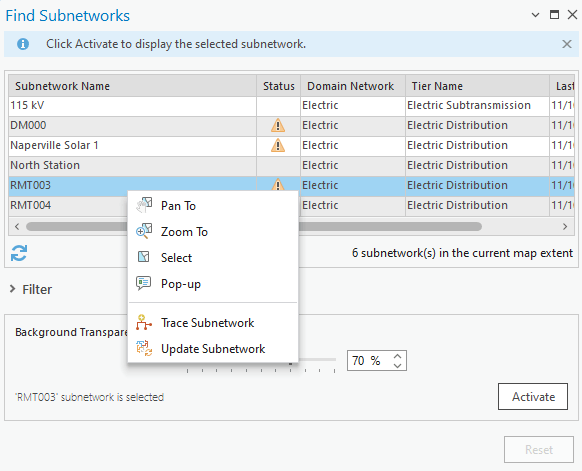
You may have noticed that each of the subnetworks in the dialog has a Status column. When you are updating a subnetwork, the subnetwork must be in a dirty state, indicated by a yellow triangle. Because you cannot the update operation, you must also save your edits before the tool will appear as enabled. You can learn more about using the find subnetworks pane in the find a subnetwork topic in the online help.
Subnetwork Errors
When the update subnetwork operation a subnetwork error it will create an error dirty area in the database associated with one or more error codes indicating the type of error discovered. You can find the full table of utility network error ids in the online help. Below is an abbreviated version of the table that describes the most common errors:
| Error Type | Error Description | Resolutions |
| Invalid Equipment | 24 / 26 / 40 / 41 / 42
An invalid feature was discovered during update subnetwork. |
1. If the affected features have been drawn correctly and should be allowed to participate in this tier of the network, then your geodatabase administrator can update your subnetwork definition to allow them to participate in this tier.
2. If you determine that the features have an incorrect asset group / asset type, then you should correct their classification.
3. If the features are correctly classified and should not participate in this tier, then you will need to correct your data to prevent them from participating in this tier. |
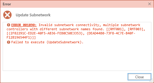
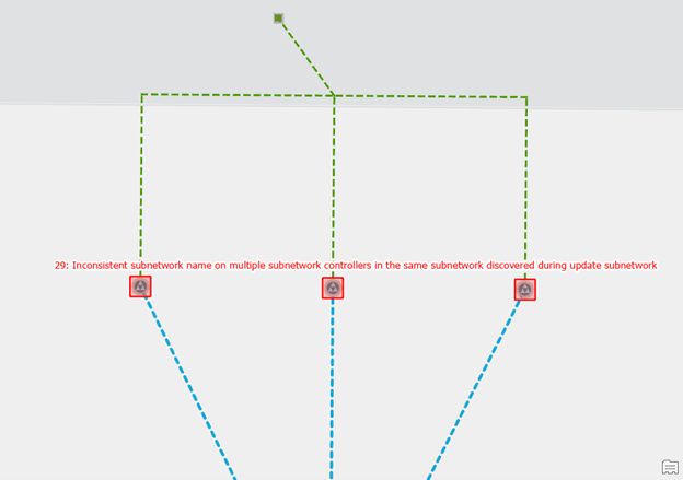
| Inconsistent Network Controller | 29
Inconsistent subnetwork name on multiple subnetwork controllers in the same subnetwork discovered during update subnetwork. |
1. If the features connected to each controller should be a single subnetwork you should update the subnetwork names associated with each controller to match.
2. If the features connected to each controller are different subnetworks and should be isolated from each other, you will need to determine why they are connected and update your data so they are isolated.
3. If only one of the controllers is active but they have different names then you will need to either isolate the backup controller from the active controller, or you will need to set the backup controller to not be a subnetwork controller. |
Inconsistent Network Name
An inconsistent subnetwork name error occurs when two subnetwork controllers share the same set of connected features but have different subnetwork names. When this happens the update subnetwork operation reports the list of affected subnetwork controllers and create errors for each subnetwork controller.
We will discuss the most common solutions to resolving inconsistent subnetwork name errors below.
Isolate the networks
If the features connected to each controller are different subnetworks and should be isolated from each other, you will need to determine why they are connected and update your data, so they are isolated.
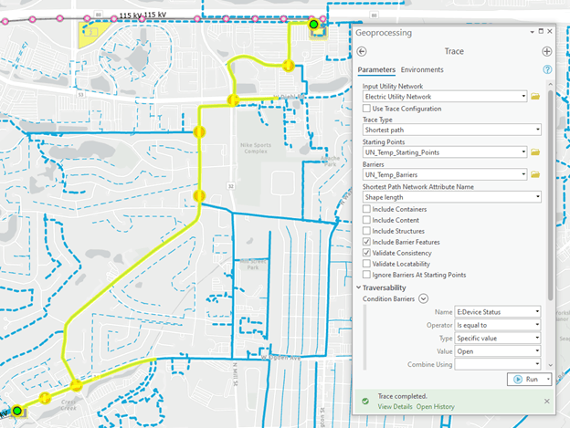
To discover how these subnetworks are connected, run the shortest path trace between the two reported subnetwork controllers. To do this perform the following:
- Place a starting point on the terminal of each subnetwork controller.
- Choose the Shortest Path trace from the Utility Network tab
- Set the Shortest Path Network Attribute Name to use shape length.
- Under Traversability, specify the Condition Barriers for your network as follows:
- Device Status is Open
- Lifecycle Status is not ‘In Service’
- (Optional) Under Output options, choose the “Aggregated Geometry” result type option under the output options to create an output set of layers containing the features.
Next, you should review the path returned by this trace. You are looking for the feature(s) that allow the two networks to be connected with each other. The most common examples are switches with an incorrect status or proposed/abandoned features that do not have the correct lifecycle status.
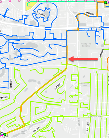
It often helps to have a special layer in your map that symbolizes the lines in your network by their subnetwork name. If you’re troubleshooting existing subnetworks, you can use the subnetwork line layer. Otherwise, you may need to use the electric line layer and either reference a legacy feeder id field or the subnetwork name field on the features themselves.
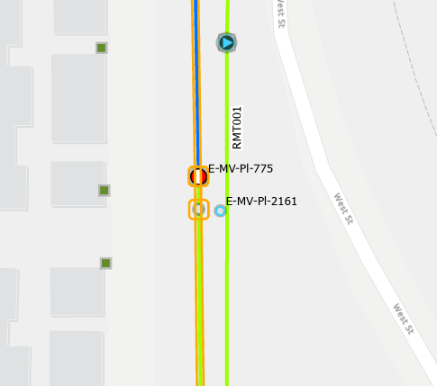
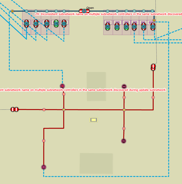
In the image below, you can see the aggregated lines layer created by the trace result overlaid on the subnetwork line layer in our map, with the location where the two subnetworks meet called out with an arrow.
If we zoom into the area and turn on the aggregated points from the trace result, we can see that the switch between these two circuits is set to closed (red with a solid line) instead of open (green with a broken line).
Before changing the operational status of a switch in the system we need to confirm its correct status with either a field crew or operation. Once we’re confident this switch should be open, we make the edit in the GIS, validate the device, validate each controller (to remove the errors associated with each controller), then rerun the update subnetwork operation on each of the subnetworks.
Update subnetwork name
If the features connected to each controller should form a single subnetwork, you should update the subnetwork names associated with each controller to be the same. This is most likely to occur when you are dealing with mesh networks where you have inadvertently named the subnetwork using the device’s name instead of the name of the mesh network itself.
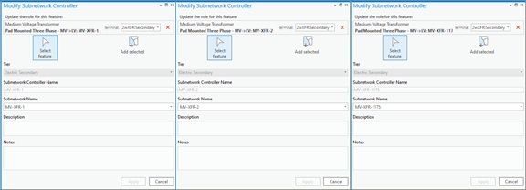
Let’s revisit the example from our previous blog where we have a spot network providing power to an important building on a customer’s campus. When we initially loaded this data, each transformer had its own subnetwork name. When we then ran update subnetwork, we received an inconsistent subnetwork controller error.
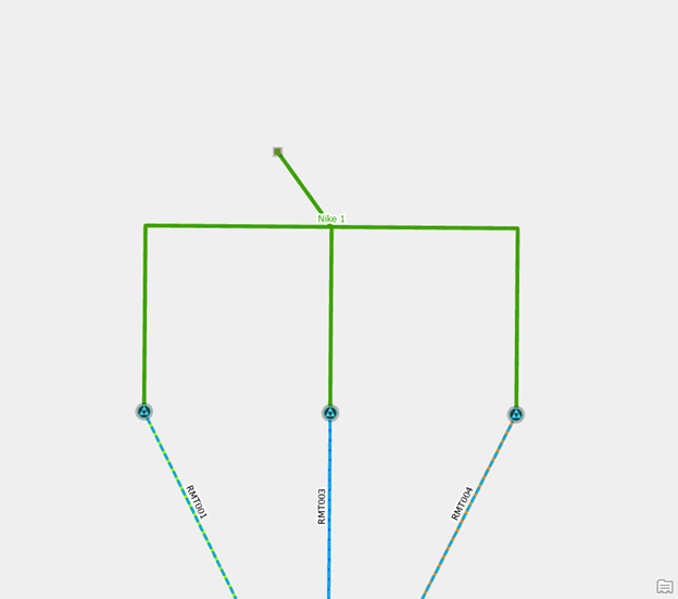
To correct the error, we remove the subnetwork controllers with each device and recreate them with a common subnetwork name. After validating the controllers and running update subnetwork, we can now see that all three controllers are providing power to a single spot network with the desired name.
Make sure you follow the steps outlined in the online help for deleting a subnetwork to completely remove the old subnetwork(s) from the system.
Remove the subnetwork
When data is first converted into the utility network many customers elect to treat all medium voltage circuit breakers as subnetwork controllers. Customers who model their substation internals will often run into problems when they first trace their subnetworks because the circuit breakers that are internal to their substations conflict with the subnetwork names on their power transformers and/or distribution circuits. You can see an example of this below:
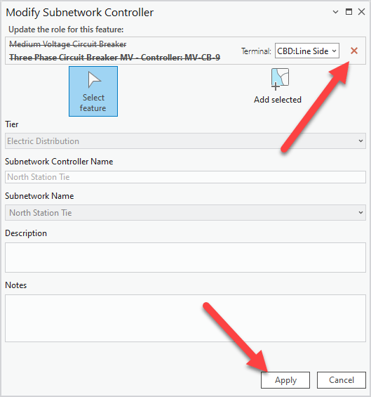
To correct the issue, you will disable the subnetwork controller on any internal circuit breakers using the Modify Subnetwork Controller pane. Select the subnetwork controller device, click the red X next to the terminal, click apply, and then use the validate topology command on the dirty area surrounding the device.
Make sure you follow the steps outlined in the online help for deleting a subnetwork to completely remove the old subnetwork(s) from the system.
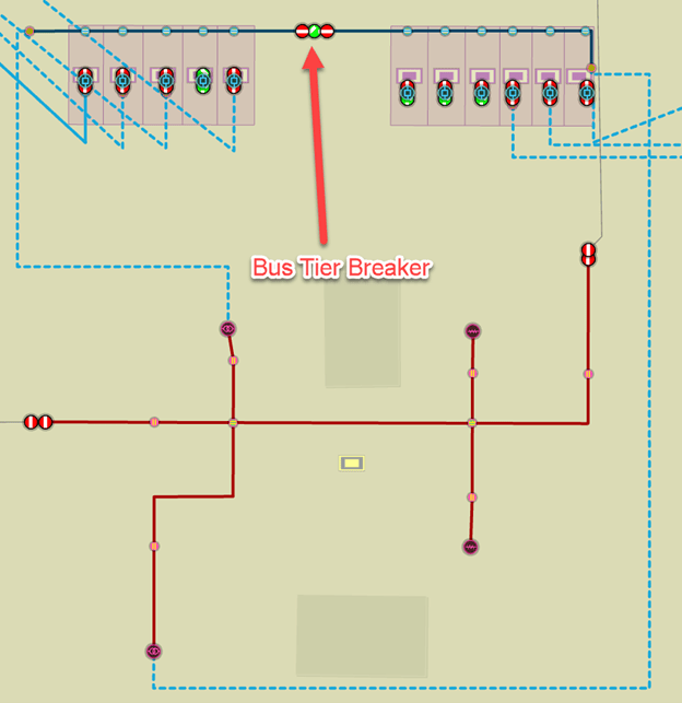
Finally, you should review the classification of the circuit breaker and ensure it is correct. In our case the medium voltage circuit breaker should be classified as a medium voltage bus tie breaker. Correctly classifying the equipment is important because it controls the connectivity rules for the feature as well as the symbology, available fields, and labels for the feature in our display.
Invalid Equipment
An invalid equipment error means that a feature was discovered in the subnetwork that, according to the tier’s subnetwork definition, is not allowed to participate in that tier.
Update subnetwork definition
If the affected features have been drawn correctly and should be allowed to participate in this tier of the network, then your geodatabase administrator can update your subnetwork definition to allow them to participate in this tier. This error most often occurs when a new asset group or asset type is the model without updating the corresponding subnetwork definitions.
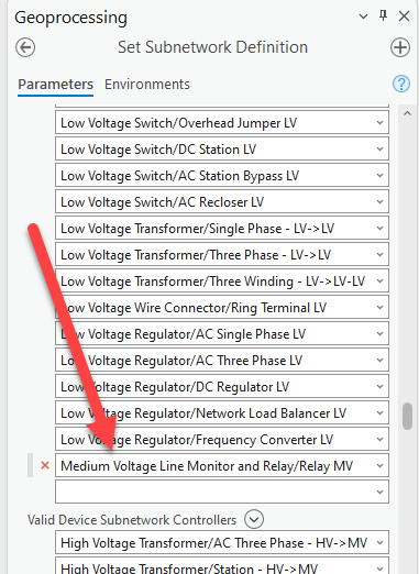
To correct the issue, we disable the topology, update the subnetwork definition, and re-enable the topology. You can see where we’ve added the MV relay to the list of valid devices in the subnetwork definition in the screenshot below:
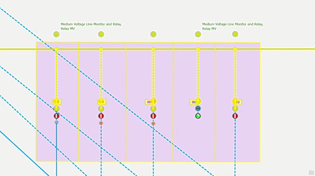
Once the subnetwork definition is corrected, we then update the distribution subnetwork to include the new relays. We see the relays participating in the distribution substation in the screenshot below:
Isolate the equipment
Because medium voltage equipment cannot be part of a transmission subnetwork it is important that all the power transformers in your distribution substations are set to be subnetwork controllers for the distribution. If they are not, then the transmission subnetworks will try to include the medium voltage inside the substation in the transmission tier. When this happens the update subnetwork operation will create an error for the first invalid line, device, or junction it discovers during the trace.
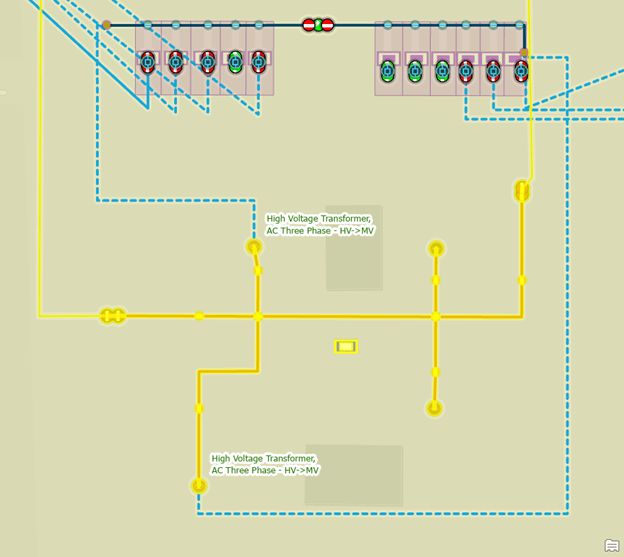
In the example below you can see that when we try to update the 115kV transmission subnetwork, it traces through one of the power transformers in our distribution substation. The error isn’t necessarily the first invalid feature discovered during the trace. In this case, it first identifies the bus tie breaker inside the substation.
To correct the issue, we use the Modify Subnetwork Controller pane to turn the power transformer into a distribution subnetwork controller. This will cause the transmission trace to stop at the power transformer and will allow the substation internals to belong to their own subnetwork.
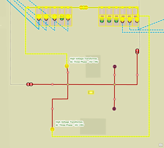
After validating our edits and updating our subnetwork we can see the transmission subnetwork stops at the power transformer.
We can also see that the entire substation is its own subnetwork.
Correct the classification
The last option to consider when correcting invalid equipment errors is whether the object(s) have the correct asset group / asset type. Connectivity rules are good at preventing this type of error from happening, but there are some edge cases where an object can be topologically correct but not allowed in the corresponding subnetwork.
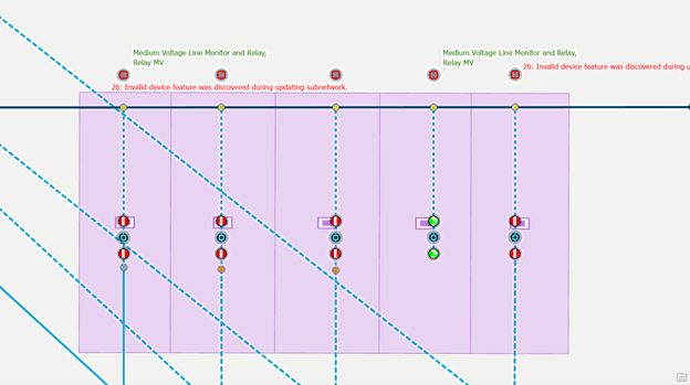
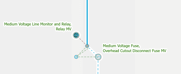
To demonstrate this, let’s consider the following example: the utility has just purchased and installed several SCADA enabled fault indicators to help improve reliability on one of their circuits. Because this isn’t a frequent operation, we aren’t sure which feature template to use. We know that the feature isn’t a normal fault indicator, so we don’t want to use that feature template. After some experimentation we determined that the Line Monitor’s Relay feature template allows us to connect the feature to an overhead line end.
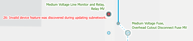
We are now able to successfully validate our dirty areas without receiving any errors, but when we run update subnetwork, an invalid equipment error is created.
If we look at the subnetwork definitions for the tiers in the electric domain network, we can begin to understand why this is a problem:
| Asset Group Name | Asset Type Name | Electric Distribution | Electric Distribution Primary | Electric Subtransmission |
| Medium Voltage Line Monitor and Relay | Fault Indicator MV | Yes | Yes | No |
| Instrument Transformer MV | Yes | Yes | Yes | |
| Programmable Logic Unit MV | Yes | Yes | Yes | |
| Relay MV | No | No | Yes | |
| Remote Terminal Unit MV | Yes | Yes | Yes | |
| SCADA Load Monitor MV | Yes | Yes | Yes | |
| SCADA Weather Station MV | Yes | Yes | Yes |
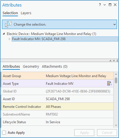
We can see that medium-voltage relays are only allowed in the subtransmission tier, and because we placed the feature on a distribution subnetwork, we received this error. After discussing the situation with other mappers in our organization, we determined that the medium-voltage fault indicator is the correct asset type to use but that we also must set the Remote-Control Indicator field to indicate whether or all phases are being monitored and put the unique identifier from the SCADA system in the Asset ID field instead of the system generated GIS ID.
Once we’ve made these changes, we are then able to validate and update the subnetwork without receiving any errors. Remember, any time you start modelling new types of equipment that you have a clear set of instructions on how to model these features in your GIS!
Conclusion
You should now have a better understanding of how to manage and update subnetworks using the Electric Utility Network Foundation. Most importantly, you are now equipped with an understanding of the most common subnetwork errors and several techniques that you can use to address these issues in your own data.
How does data quality assurance differ from error management? Isn’t error management part of a data quality assurance process? What are the checks we recommend you include in your data quality assurance process? We will answer all these questions and more in our final blog in this series where we discuss the tools and processes you can use to implement a more thorough data quality assurance process for your electric networks.
If you’re interested in more learning content related to the utility network check out the Learn ArcGIS Utility Network for Electric learn series as well as these hands-on tutorials related to this article:


Commenting is not enabled for this article.