Introduction
In our previous articles, we discussed how to use ArcGIS Pro and the Gas and Pipeline Referencing Utility Network Foundation to create, manage, and validate subnetworks. If you haven’t read the previous articles yet, I strongly recommend you go back and read part one and part two as they introduce key concepts and techniques you’ll need to know to understand this article. You can find all these articles, and more, in the ArcGIS Utility Network for Gas and Pipeline reading list.
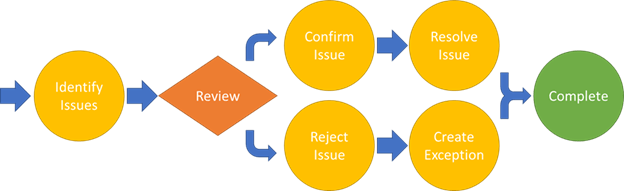
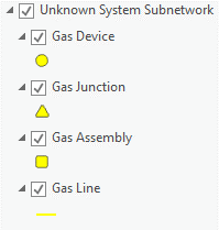
In addition to managing errors reported by the application, we can use several other techniques that leverage the ArcGIS Utility Network and ArcGIS Pro capabilities as part of our data quality assurance program. These techniques allow us to find features that indicate there are data quality issues in an area that require a user to review. Every utility has its own set of business rules and quality assurance checks that they perform, and hopefully, you can incorporate the techniques discussed in this blog into your processes going forward. The following diagram provides an example of customers’ basic quality assurance process to log, review, and resolve issues.
The following table provides a summary of the recommended quality assurance checks for gas and pipeline subnetworks:
| Error Type | Resolutions |
| No Parent Subnetwork | 1. If the affected feature is not active or does not need to participate in a parent subnetwork, then this is not an issue.
2. If the affected feature should participate in a parent subnetwork, then you will need to determine why the parent subnetwork was unable to reach your current device. |
| Inconsistent Parent Subnetworks | 1. If the affected feature is allowed to participate in multiple parent subnetworks, then this is not an issue.
2. If the affected feature should only participate in a single-parent subnetwork, then you will need to determine which system it belongs to and isolate it from the second system. |
| Not Connected | 1. If the affected feature is not active or does not need to participate in a subnetwork, then this is not an issue.
2. If the affected feature should participate in a subnetwork, then you should review the condition barriers and propagators associated with your subnetwork to determine why the subnetwork was unable to reach the feature. |
Many of these quality assurance checks require that subnetwork names are populated. If you read our previous blog, you will remember that this field is populated when you run the update subnetwork tool. Because of this requirement, an important part of the quality assurance workflow is to run validate topology and update subnetwork to ensure all your subnetworks are error free before you begin!
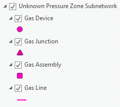
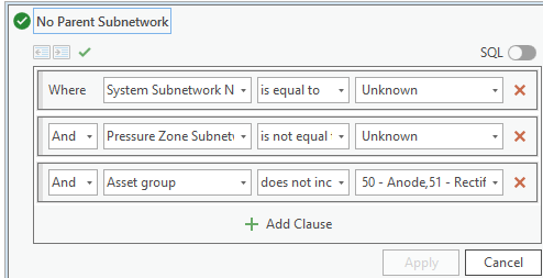
Unknown Pressure Zone Subnetwork
In the gas model, every feature that belongs to a pressure zone should also belong to a system. Common exceptions to this rule can include lines between system controllers and pressure zone controllers, cathodic protection features, or features that are not in service.
A common approach for identifying this issue is to validate the data using a tool like ArcGIS Data Reviewer or to have a layer in your map that highlights the features using definition queries. The Gas and Pipeline Utility Network Foundation solution has an example map called the Gas and Pipeline Data Audit map that includes several of layers that can be used to assist in quality assurance. To audit the pressure zone subnetworks you can create a copy of the “Unknown System Subnetwork” layers from the Gas and Pipeline Data Audit map and modify its definition query to verify the PressureSubnetworkName field instead of the SystemSubnetworkName. You can find an example of what this would look like below:
Verify correctness
The first thing to investigate when looking at a feature that doesn’t currently have a pressure zone is whether or not it should belong to a pressure zone. Remember that every in-service asset in a pipe network is pressurized and therefore should be associated to a pressure subnetwork. But … what about those assets which are not in-service?
A common example of a scenario where features should not belong to a pressure system is when proposed or abandoned features haven’t had their lifecycle status updated in the GIS and still appear in-service. If your company uses a job or work order polygon to track work this can make it easier to identify these situations, as this they will allow you to access the work sketches associated with the area.
Identify path to controller
If you’ve found features in an area that don’t participate in a pressure zone, but you believe they should, the first thing you need to determine is how they should be connected. In the example below we can see an area of our network that is not connected to the rest of the system.
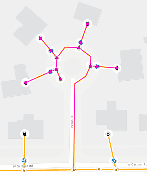
If we zoom in on the tee which the lateral is connected to, we can see that the lateral has overshot the tee. If the lateral were drawn in ArcGIS Pro, snapping would have prevented this error. This indicates that the lateral was likely drawn in or imported from an external system.
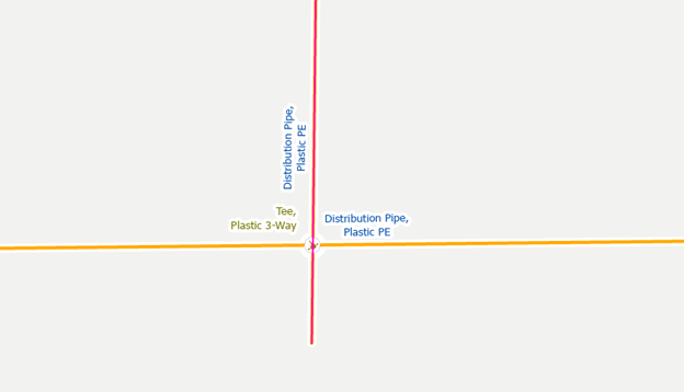
To correct the issue, we edit the vertices of the main and snap it to the lateral. After validating the topology for the edit and updating our subnetwork this area will now display as an active part of the pressure zone and gas system.
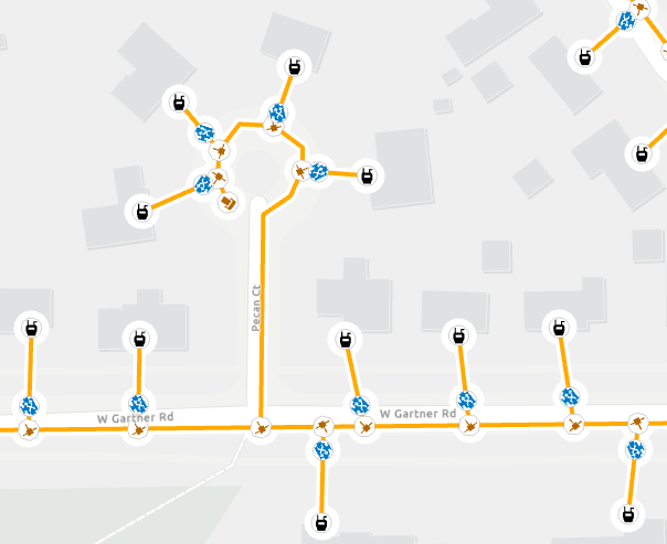
Unknown System Subnetwork
We expect every in-service feature in our pipeline network to participate in either the gas or cathodic protection system. The utility network was originally designed to require this; however, this constraint was relaxed due to the need of many customers to incrementally loading their data.
The Gas Utility Network Foundation solution includes an example map that can be used for quality assurance called the Gas and Pipeline Data Audit map. You can use the “Unknown System Subnetwork” layer to find the active, non-cathodic equipment that does not belong to a system subnetwork.
To accurately capture the scenario we described above, we need to adjust this query to ensure we are only looking at features that belong to a pressure zone that do not yet have a system subnetwork.
Verify correctness
If you identify an entire pressure zone that doesn’t belong to a system subnetwork because the gas supply for the pressure zone hasn’t been loaded yet, you will need to create an exception for this area.
Once you’ve loaded the gas supplies for the area you will want to revisit any affected zones to verify that all the pressure zones are properly connected.
Identify path to controller
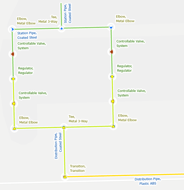
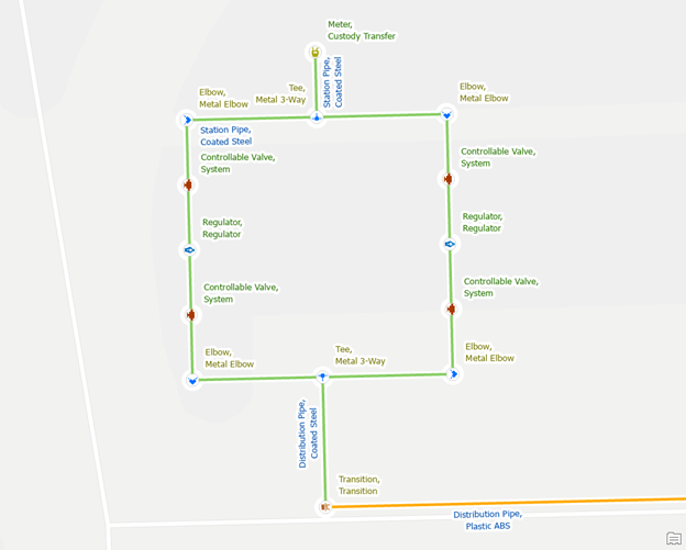
If you’ve found a pressure zone that doesn’t participate in a system subnetwork, but you believe it should, then the first thing you need to determine is how it should be connected. In the example below we can see our pressure zone does not have a system name even though it appears to be connected to a gas supply.
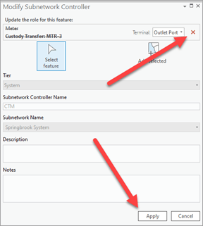
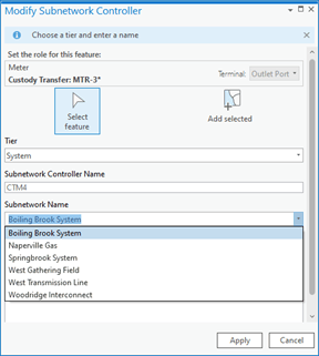
First, we verify that the custody transfer meter is configured to be a subnetwork controller and to see which port the subnetwork is associated with using the modify subnetwork controller tool.
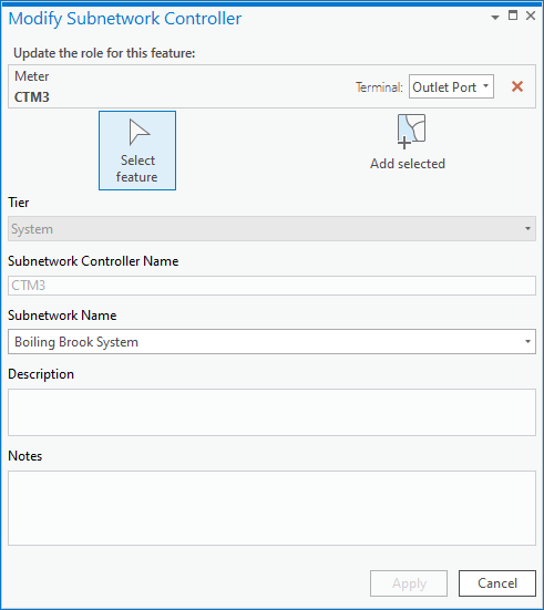
Next, we use the Modify Terminal Connections pane to verify that the station pipe is connected to the correct terminal on the custody transfer meter.
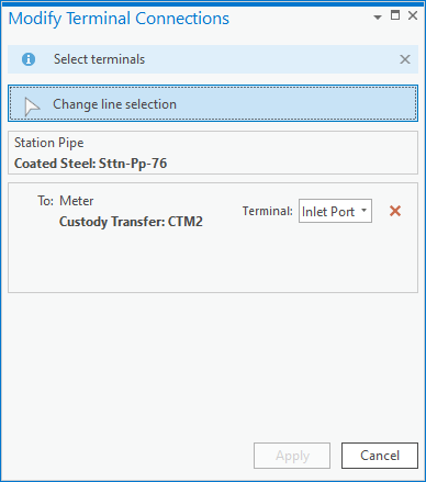
We have now discovered the problem; the pipe is connected to the wrong terminal. We must connect the station pipe to the terminal associated with the system subnetwork to connect the station to the system. With the dialog still open select the outlet port to connect the station pipe to the outlet port and click apply.

This will create a dirty area on the pipe we modified. First we run the validate topology tool to validate the terminal change and update the network topology. Next we run the Update Subnetwork operation on the gas system to pressurize the entire area.
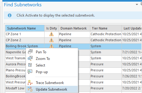
Once this is completed, we can confirm that the zone is now part of the gas system.
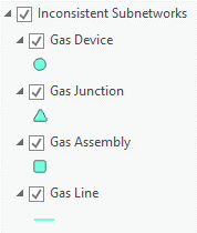
Inconsistent Parent Subnetworks
Typically, each pressure zone will only belong to a single system subnetwork in your network. However, depending on your naming standards for your system subnetworks you may have some areas in our network where pressure zones are being served by different systems.
Verify correctness
You can identify these areas by looking for pipes that have multiple subnetwork names (systemsubnetworkname like ‘%::%’ or pressuresubnetworkname like ‘%::%’). If you determine that the areas are part of two systems or pressure zones, then you can create an exception for this issue.
Rename Parent Subnetwork
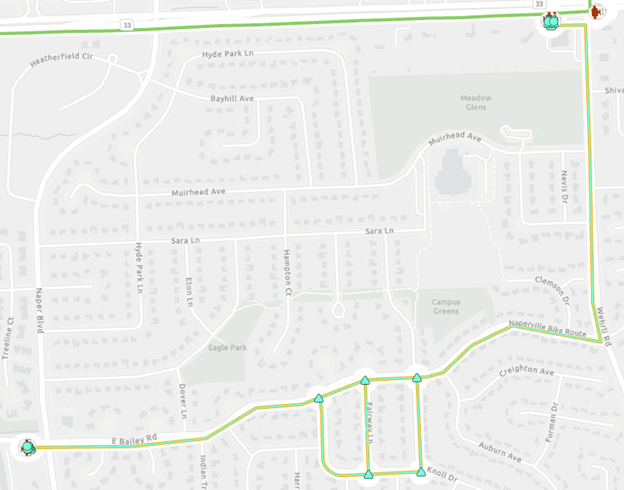
If you find an area with these errors, you will need to decide if the two parent systems should be considered the same system. An engineer or system planner who is familiar with the layout of your system should be able to answer this question easily. In the example below we see a direct path between both systems so we decided they should be the same system.
To fix the issue you should use the Modify Subnetwork Controller pane to update the subnetwork names of one or both subnetworks to match. To do this you must remove the old subnetwork controller’s terminal assignment from the controller, then assign the new subnetwork.
Once you have updated your controller(s) you will validate the topology for the stations, then run update subnetwork on the new system subnetwork and the old system subnetwork. This will update the pressure/system subnetwork name fields which will resolve the error.
Isolate from the second controller
If you’ve reviewed the errors and have determined that they shouldn’t belong to the same system, then you will need to isolate your pressure zone from the system it should not be connected to.
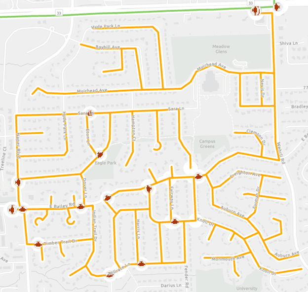
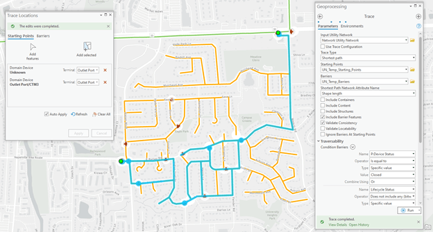
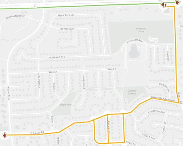
You can use the shortest path trace to identify the path between each system controller. You can configure the shortest path trace by using the shape length as your network attribute and by setting the condition barriers for the trace to match those of your system tier. If you are unsure what the condition barriers are for your network you can find this information in the Tier section of the Network Properties page on the utility network layer in your map. You can see the standard configuration below, but your model may have additional barriers or fields may be named differently.
The selected features show the path between the two controllers. Review the features along this path to identify a potential resolution to the problem. At first glance, we can see a system valve that we could potentially close to isolate the two systems, but we would want to confirm with an engineer before modifying the status of a system valve.
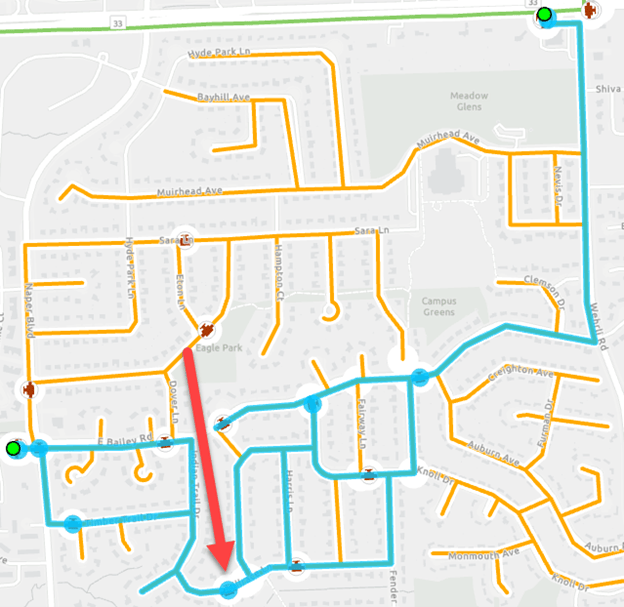
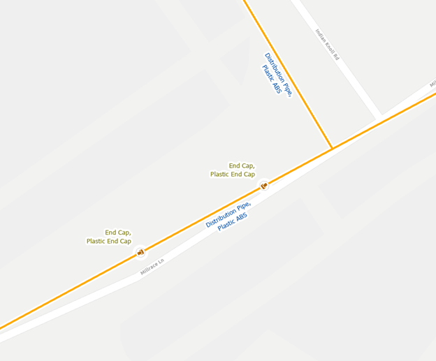
Upon a closer review, we can see there are two end caps placed on one of the mains, but the main itself has not been split or trimmed.
In this case, we can research the work orders performed in this area, and we will likely discover that the section of main between these two systems was abandoned but the GIS wasn’t properly updated. We can resolve the issue by splitting the main at each end cap, abandoning the middle segment, then trimming the ends of the abandoned main.
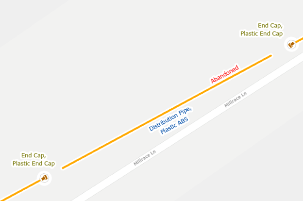
Once we validate our topology for this area and update the subnetworks, we will see the error is resolved.
Conclusion
Now that you’ve stepped through the examples in this blog you should be familiar with the quality assurance techniques you can use to find and features that don’t belong to a subnetwork, or belong to too many subnetworks, along with several approaches for correcting these issues.
I hope you find these techniques useful to keep your data clean so you can get the most out of your gas and pipeline GIS data! If you’ve read the previous two blogs in this series, you are now fully prepared to start creating and managing your gas and pipeline data in a utility network using subnetworks! You can find links to the other gas and pipeline blogs below and I recommend you download and start getting familiar with the Gas and Pipeline Referencing Utility Network Foundation from the ArcGIS Solutions team.
If you’re interested in more learning content related to the utility network check out the Learn ArcGIS Utility Network for Gas and Pipeline learn series as well as these hands-on tutorials related to this article:


Commenting is not enabled for this article.