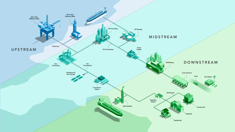
Today’s natural gas pipe networks are an engineering marvel. In North America, this interconnected network consists of nearly 3 million miles of gathering, transmission, storage, and distribution subsystems. Another marvel of this pipe network is that it uses only pressure to push the natural gas molecules through this vast network. Understanding of pressure and how it is used to move these natural gas molecules is the secret sauce for understanding the engineering of gas pipe networks. One of the most exciting and powerful features that the utility network provides to gas and pipeline customers is its ability to understand pressure. This understanding allows the ArcGIS Utility Network to digitally represent this engineered pipe network and its hierarchical subnetwork of system, pressure, and isolation zones.
Because the tools and processes used to manage this GIS information are new, we have put together a series of blog posts to introduce you to the language and tools used by the ArcGIS Utility Network to create, manage, and perform quality assurance on the correctness of your gas and pipeline systems. These articles are written using the data model and configuration provided by Esri’s Gas and Pipeline Referencing Utility Network Foundation solution. If you’re interested in more content like this, I recommend you check out the ArcGIS Utility Network for Gas and Pipeline reading list as well as these hands-on tutorials related to this article:
- Create and Manage Subnetworks
- Edit and Validate Subnetworks
- Perform Quality Assurance on Subnetworks
What is a Subnetwork
Before we go too much further, we need to discuss the concept of a subnetwork in the utility network. Most networks can be broken down into different areas based on the equipment that is supplying or regulating service. Each of these areas is referred to as a subnetwork, and every feature that is responsible for managing a subnetwork is called a subnetwork controller. We use these general terms because the utility network is used to model many types of networks and each network has its definitions for the different types of subnetworks it manages. Each type of resource managed by a utility network is called a domain network; the definitions for the types of subnetworks that each domain network manages are called tiers.
With those definitions out of the way let’s look at the tiers associated with the gas and pipeline domain in the Utility Network. The tiers associated with the model are Gas System, Gas Pressure, Gas Isolation, and Cathodic Protection. This article is focused on modeling systems and pressure zones, but the techniques described here also apply to cathodic protection, and isolation zones.
The following diagram shows how the gas tiers are organized using a hierarchy where each isolation zone is contained within a pressure zone, and each pressure zone is contained within a gas system. We will be revisiting this structure in later articles when we examine what happens when we have a pressure zone that belongs to multiple systems or no system at all!
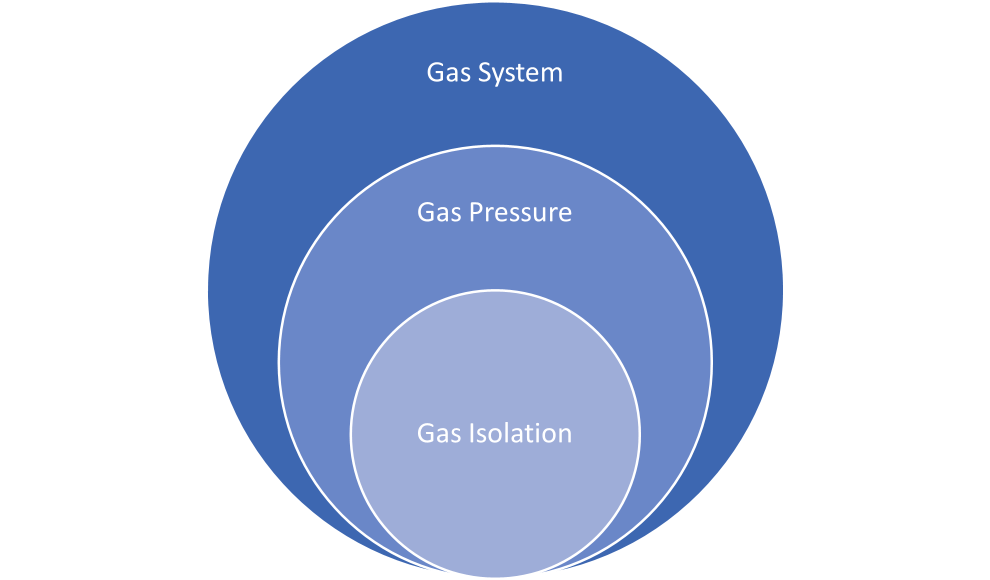
For those of you who aren’t familiar with how gas models are constructed, here is a brief definition of what each of these tiers does:
- Gas System – A gas system is an area that all shares the same gas sources. Each system often has more than one source, with gas either being pumped out of the ground by a wellhead or being purchased and metered from another utility at a custody transfer meter.
- Gas Pressure – A gas pressure subnetwork, often referred to as a pressure zone, is a section of the gas system that is designed to operate at a specific pressure level. This pressurization is managed by pressure-regulating devices such as regulators to decrease pressure, and compressors to increase pressure. Regulating devices are typically located within a gas facility such as a regulator station, town border station, or compressor station.
- Gas Isolation – A gas isolation subnetwork, or isolation area, is a predetermined area of the network with a known set of valves that can be operated to isolate a subsection of a pressure zone for maintenance or emergency purposes. Part of designing a reliable system is ensuring that every customer is part of an isolation zone and that each zone is a reasonable size and has multiple paths to a given gas source.
In addition to these three gas tiers, there is also a fourth Cathodic Protection tier. A cathodic protection system is a subset of the pipe network which is electro-chemically configured to mitigate corrosion of its metallic components.
Now that you’re familiar with the purpose of each tier, let’s walk through a few examples of how to create subnetwork controllers in a sample dataset so we have a fully connected gas system with several pressure zones.
Creating a Subnetwork Controller
First, let’s talk about how to create a subnetwork controller. To create a subnetwork controller, you need at least six pieces of information
- Tier Name – This is the tier that the new subnetwork will belong to.
- Terminal – This is the terminal that the subnetwork will originate from. You will find specific examples below on how to select the correct terminal.
- Subnetwork Controller – This is the device that will act as the source for the subnetwork.
- Subnetwork Controller Name – This is a unique identifier for the device.
- Subnetwork Name – This is the name of the subnetwork it controls. If a subnetwork has multiple controllers, then they should all have the same subnetwork name, but different subnetwork controller names.
- Line(s) – Which line(s) are connected to the terminal associated with this subnetwork
Even if you’re not familiar with the utility network model, you should be able to quickly identify all of these pieces of information, except for the terminal. Every subnetwork controller is required to have at least two terminals. Depending on the type of device they are associated with these terminals can either be directional or bi-directional. In the case of a compressor the upstream terminal is the low pressure inlet and the downstream terminal is the high pressure outlet. The terminals on a subnetwork controller allow the system to clearly delineate the boundaries of subnetworks, and in the case of pressure differences ensure that subnetworks flow in the correct direction.
Once you’ve identified these six items, you’ll want to look at the lines connected to each of your controllers and figure out which terminal on the device they are connected to. This is a straightforward process for things like custody transfer meters and compressors, but it may be more difficult for devices like regulators if you don’t have clearly defined boundaries for your pressure zones.
Topology Errors
The first thing we need to check before we create this system is to make sure that the topology for the system is valid. You can still create a gas system if you have errors in your data, but you won’t be able to trace or fully update it until all the errors in the system are resolved. For this reason, we recommend utilities adopt a zero-tolerance policy for dirty areas and errors in their database! If you find yourself needing some help resolving these errors I recommend you read the blog I wrote for how to resolve gas topology errors or read the online help topic about error management. The quickest way to check the number of errors in your utility network is to right-click the utility network layer in your map, select Properties, then look at your Network Properties.
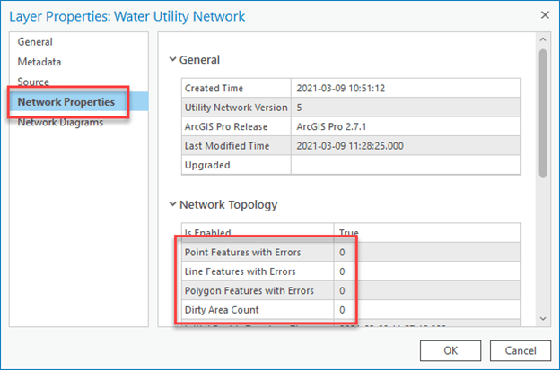
If you see zero errors and zero dirty areas, then you’re in a perfect place to start creating subnetworks! If you have dirty areas, but no errors, then you need to use the validate topology tool to resolve those outstanding issues. If you have errors in your topology then you’ll need to resolve them. Check out our previous blog for a guide to resolving the most common topology errors for gas networks if you need a refresher.
Once we have validated all our dirty areas and resolved all our errors, we’re ready to start making subnetworks!
Area of Interest
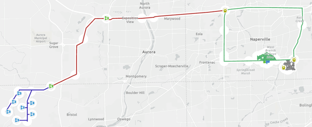
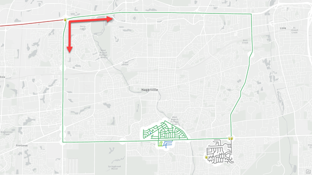
In the following examples, we will be creating three systems and a pressure zone for the following area in the Gas and Pipeline Referencing Utility Network Foundation solution. We have a gathering system on the west area of our map where we are extracting natural gas. This gas is connected to a high-pressure transmission system that provides gas to all the customers in our distribution system on the eastern area of our map. Within our distribution system, we have a high-pressure ring surrounding our city, with the city itself having several pressure zones.
Creating a Gas Gathering System
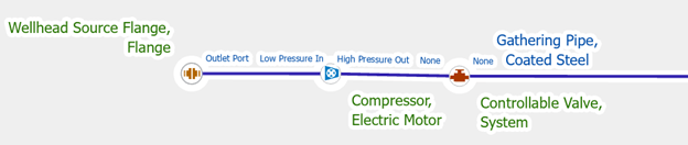
A gathering system is a collection of one or more wellheads that are all collecting natural gas and either storing it for later use or providing it to a transmission system. In our example below we have seven different wellheads acting as a single system.
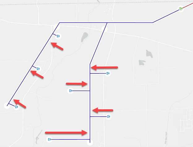
Because this system has seven controllers, we need to create each wellhead as its subnetwork controller with the following values:
- Subnetwork Controller – We will use the Modify Subnetwork Controller pane to select each wellhead.
- Tier Name – This will System
- Terminal – We select the Outlet port on the wellhead flange because it is the downstream terminal on this device and gas flows away from the wellhead.
- Subnetwork Controller Name – This is the name of the wellhead, it will be different for each controller
- Subnetwork Name – This value will be the same for each controller since they are all providing gas for the same system.
- Line(s) – Once we’ve created the subnetwork controller, we will need to ensure that the pipe is connected to the correct terminal on the flange. If there is also a compressor near the wellhead, we will want to ensure that the terminals on the compressor are configured to take the low-pressure gas from the wellhead and output higher-pressure gas to the rest of the system.
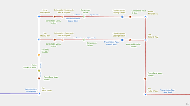
Creating a Gas Transmission System
Our transmission system consists of two compressor stations, one connects to our gathering system, and another is located along the pipeline to maintain pressure. These compressor stations ensure that the gas transmission system maintains a consistent, high pressure.
We will create a subnetwork controller for each of the compressors in the compressor stations shown on the above map, using the following information:
- Subnetwork Controller – We will use the Modify Subnetwork Controller pane on the compressor in each of our compressor stations.
- Tier Name – This will be the System tier
- Terminal – We select the High Pressure Out port on each compressor because this is the downstream terminal, and we associate the transmission system with the compressors that are providing and maintaining that pressure.
- Subnetwork Controller Name – This is the unique name of the compressor; it will be different for each controller and there may be multiple compressors in each station
- Subnetwork Name – This value will be the same for each controller since they are all providing gas for the same system.
- Line(s) – Once we’ve created the subnetwork controller, we will need to ensure that the nearby pipes are connected to the correct terminals on the compressor. The gathering system should be connected to the low-pressure in terminal of the compressor and the transmission system should be on the high-pressure out terminal on the compressor. If you track the designed operating pressure of the lines, we can confirm that the pipes are different operating pressures.
Creating a Gas Distribution System
In our sample dataset, our gas distribution system is fed entirely from a town border station connected to our transmission system, in a real-world scenario there would likely be multiple stations supplying gas to this system.
We navigate to our town border station and create a subnetwork controller for the custody transfer meter using the following information:
- Subnetwork Controller – We will use the Modify Subnetwork Controller pane on the custody transfer meter in the town border station.
- Tier Name – This will be the System
- Terminal – A custody transfer meter tracks the amount of gas received from the transmission system and delivered to the distribution system. Because the distribution system is on the downstream side of the custody transfer meter, we want to assign the subnetwork to the outlet port.
- Subnetwork Controller Name – This is the unique name of the custody transfer meter
- Subnetwork Name – This value will be the name of the distribution system. If we modeled other custody transfer meters for this system, they would all have the same subnetwork name.
- Line(s) – Once we’ve created the subnetwork controller, we will need to ensure that the pipes are connected to the correct terminals on the custody transfer meter. The transmission pipes should be connected to the inlet port and the station should be connected to the outlet port. This will ensure that the meter is configured to record the gas that is flowing from the transmission system to the distribution system.
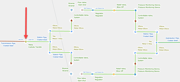
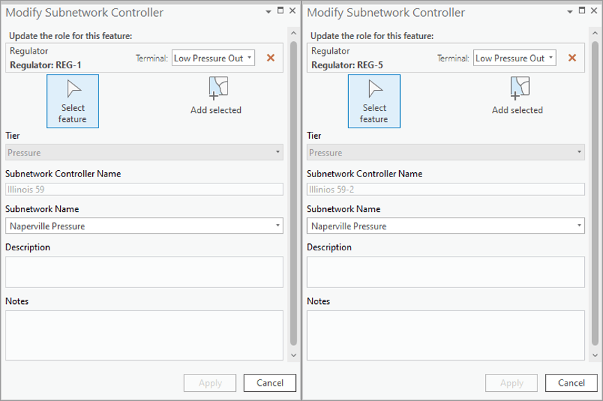
Creating a Gas Pressure Zone
In the same town border station as our custody transfer meter, we also have two regulators that are maintaining a 125-psi pressure system that surrounds the city.
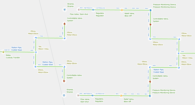
Use the Modify subnetwork Controller pane to set each regulator as a subnetwork controller. Ensure you select the low-pressure out terminal on the regulator to ensure the subnetwork is associated with the lower pressure zone. Each controller name needs to be unique for each controller device, but because this pressure zone has multiple controllers, we will give each regulator for this pressure zone the same subnetwork name.
Next Steps
Now that you’ve seen how to create gas systems and pressure zones using the Gas and Pipeline Referencing Utility Network Foundation you should start developing a plan for subnetwork management. Ask yourself the following questions:
- What systems do I have data for?
- Are there gathering or storage systems?
- Is there data to support cathodic protection systems?
- What are the names of the systems in my data?
- Where are the gas sources for each system?
- Where are there interconnects / custody transfer meters with other utilities?
- What are the names of the stations associated with each system?
- Where are the pressure zones in my data?
- How is the pressure increased or regulated in each of these zones?
- What are the names of the equipment associated with each zone?
Leveraging the Utility Network subnetwork capabilities is allowing natural gas organizations to better represent real-world pipe networks. A representation that helps everyone in the organization to better understand the engineering marvel they have built and maintained.
With this information, you can start creating your gas subnetworks! You can find the entire collection of these articles in the Learn ArcGIS Utility Network for Gas and Pipeline learn series as well as these hands-on tutorials related to this article:


Commenting is not enabled for this article.