Updated 5/19/2025 for ArcGIS Enterprise 11.5
Updated 6/13/2023 for ArcGIS Enterprise 11.1
Introduction
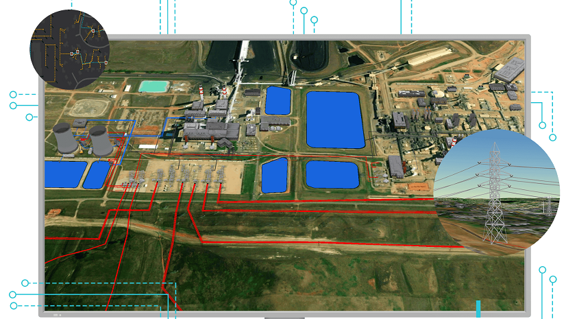
Enterprise GIS is a powerful tool for integration because it allows a company to model logical, spatial, and topological relationships for all its data. At utility companies, this is especially important because GIS is the system of record for how the network distributes resources to customers. In earlier articles, we have provided an overview of the integration strategies, as well as examples of common utility network integrations.

The utility network includes many tools that allow users to analyze network data to produce different graphical or tabular results. However, there are limits to what is possible without customization. This article will show GIS Analysts and Developers the ways they can extend the utility network’s analytical capabilities by extracting network information from a utility network. Once extracted, these files can be used for local analysis or to or transform the network topology for analysis in other systems.
We will focus on answering the following questions:
- What are the tools used to extract network data from the utility network?
- What result types are available with these tools?
- How parameters are available to control these tools?
- How do I use the output from these files?
- What are the performance considerations for this approach?
For a more detailed description of how to process and transform the files representing the utility network, read the Parsing Utility Network Exports article on the ArcGIS Utility Network community channel.
Extracting Network Data
The two recommended techniques for extracting network data are to use the Export Subnetwork and Trace methods of the utility network. You can get familiar with these methods using geoprocessing tools in ArcGIS Pro. Once you’re comfortable with these methods you should review the APIs outlined in the integrations overview article, to see which API best matches the capabilities and performance required by your interface.
Export Subnetwork

The export subnetwork tool allows you to extract all the connectivity and network feature information for a specific network. If you just need to know which features belong to or support a subnetwork it is much easier and faster to use attribute queries to extract this data. The export subnetwork tool shows a fine-grained model of how features connect in the network. Engineering analysis and outage management systems often rely on this tool to import connectivity and features from a utility network.
The Export Subnetwork tool can be run against a local file or mobile geodatabase but cannot be run directly again an enterprise geodatabase. To analyze an enterprise geodatabase, you must publish a feature service containing the utility network and the network classes that it controls. The tool can then be run against the utility network in the published feature service.
Export subnetwork requires the subnetwork being exported to be clean. Because some utility networks don’t manage the status field on their subnetworks (the Manage IsDirty configuration in their subnetwork definition is set to False) those subnetworks will always be dirty. To work around this, you can use the Trace tool to export JSON for dirty subnetworks. You can learn more about why some customers don’t manage the status field in the Understanding Subnetworks: Status article.
You can learn more about this tool by reading the following resources in the online help:
- Export SubnetworkTool (Geoprocessing)
- Export Subnetwork Operation (REST)
- Export Subnetwork Method (ArcGIS API for Python)
For information on how to interpret the JSON results of this tool, read the Parsing Utility Network Exports article on the ArcGIS Utility Network community channel.
Trace

When the data you need to extract is in a single network the export subnetwork tool is the obvious choice for flexibility and ease-of-use. You should use the trace tool when you need to extract or analyze data from your network using other criteria, like everything downstream of a certain device. The trace tool will query network features, perform basic network analysis in memory, and output the results to JSON. This is one of the most powerful and challenging tools you can use to develop an interface because it requires a strong understanding of the network model. You must carefully design interfaces with scalability and performance in mind when using this tool, you can read more about this in the performance section of this article.
Customer Information Systems (CIS) and GIS often share information about how a customer connects to the network. This information often includes information about the location of the meter as well as how and where the customer connects to the network. As the mappers edit the GIS this information will change and the only way to truly compare these two systems is by using traces to confirm the topology in the GIS matches the information in the CIS. Depending on how large your network is this would require tens or hundreds of thousands of traces every night. I describe several techniques below that will help you design your interface to scale and meet these challenges.
You can learn more about this tool by reading the following resources in the online help.
- Trace Tool (Geoprocessing)
- Trace Operation (REST)
- Trace Method (ArcGIS API for Python)
For information on how to interpret the JSON results of this tool, read the Parsing Utility Network Exports article on the ArcGIS Utility Network community channel.
Result Types
Now that you’ve seen how to extract data from a utility network let’s look at how the different result types can be used to control what information is extracted. There are four different result types that are output to JSON:
Note: Elements can also be output to JSON, but this result type is typically not used for network integration purposes.
Connectivity
Connectivity is one of the most common, yet most complex result types for trace and export subnetwork. This result type adds an undirected graph of the topology of the network to the trace result. There are plans in future releases to add a result type for a directed graph, but this has not been implemented as of the writing of this article.
A junction that has multiple terminals may be represented multiple times in the JSON output. When analyzing JSON files, you should uniquely identify junctions using the Network Source ID, Global ID, and Terminal ID of the junction of the from/to elements.
An edge element that has a connectivity policy of Any Vertex may have junctions or devices connected midspan. In this case, there may be multiple connectivity elements within the JSON to represent each segment of the edge. When analyzing JSON files, you should uniquely identify edges using the Network Source ID, Global ID, Position From, and Position To of the via element.
The from and to elements included in this export are based on the from/to location on the via element. In the case of a line this will be its first/last vertices and in the case of an association this will be the from/to elements. To determine flow direction (upstream / downstream) using this structure you must manually trace the connectivity while respecting the condition barriers and propagators of the network. You can see an example of the JSON connectivity elements in the file below.

Containment and attachment associations
By default, the export subnetwork tool only extracts the devices, lines, and junctions that move resources in your network. When your trace configuration includes containers and structures, the tool will include the structures and assemblies that contain or are attached to features returned by your analysis. This is important because it will allow you to automatically include important assets like vaults and assemblies that have important attributes about the network features. You can see an example of the output in the included JSON sample.
Unfortunately, the result type doesn’t include related non-network data. If you need to include information related to your network features, you will need to use the Related Records result type.

Features
This result type allows you to include information about the features and rows returned by the analysis. In addition to include network attributes, you can also include information not stored in the network like the geometry of features or attributes that are not associated with a network attribute.
While this additional information is convenient, including information not stored in the network topology means additional information must be acquired from the database after the analysis portion of the trace finishes.
Related Records
This result type allows you to attribute values from rows related to the trace results, even when they are non-network features. This is useful for customers who want to make use of information about equipment configuration or settings that is stored in tables related to network features but that don’t participate in the utility network.
Other Parameters
The trace and export subnetwork tools have many parameters that control their output. We will describe some of the most important parameters here. In the older releases of ArcGIS Enterprise, the export subnetwork tool has provided more options for how to output results, but in newer releases the trace and export subnetwork operations have equivalent output capabilities. Below we describe how to best use the following parameters when performing network analysis:
Trace Configuration
A trace configuration allows you to control how a trace behaves, and which features should be returned. Every subnetwork has a default configuration that is used when you trace, validate, or export a subnetwork. The trace and export subnetwork tools allow you to override any default trace configurations that alter this behavior.
Export Subnetwork uses the trace configuration defined for the subnetwork being exported, but when using the trace tool to extract data you must provide a trace configuration. When possible, you should use named trace configurations stored in the database to run trace. This not only saves you from hard coding trace configurations but also makes it easier to test and maintain the trace configuration if any configuration changes are made to your utility network.
It is possible, but uncommon, to use a different configuration when exporting subnetworks. In our next article we show how you use a different trace configuration to include proposed or normally de-energized features in your exports.
You can learn more about trace configurations through the following online resources:
- Trace Configuration concepts (ArcGIS Map SDK for .NET)
- Trace Configuration properties (REST API)
- Exploring the trace framework (Article)
Admin Export
The export subnetwork tool has an option to export with acknowledgement, also known as an admin export. Running the tool in this mode will update the last exported timestamp on the corresponding subnetwork record. This timestamp makes it easy for any integration, even ones that don’t trace, to limit their processing to only the networks that have been updated since they were last exported.

Output
This section describes some of the important considerations for extracting data from the utility network. A more detailed analysis of how to interpret and use the JSON output can be found in the Parsing Utility Network Exports article on the ArcGIS Utility Network community channel.
Attribute Descriptions
When you select this option, it will include coded value descriptions for attributes in your exported file. This is an important feature for integrating with non-GIS systems since it provides the underlying database values along with human readable values. This makes the file much easier to consume and understand for users who aren’t familiar with the inner workings of GIS. Here you can see a JSON sample that includes attribute descriptions.

If you do not select this option, the resulting file will be much smaller but will only contain the codes and underlying values from the database.
Source Mappings
Any time a network feature is referenced in the JSON output it includes the Object ID, Global ID, and Network Source ID of the feature. While the meaning and purpose of the Object ID and Global ID values is well understood by most GIS professionals, the Network Source ID is something unique to the utility network.
The Network Source ID is an integer that uniquely identifies a layer that acts as a network source for a given utility network and is persisted in the geodatabase. This id is useful because it allows you to identify a particular layer (device, junction, etc) without needing to refer to the feature class name, layer id, or some other identifier that could potentially change.
The next question is, of course, how do you translate this network source id into an actual layer name when you do need to understand what layer a particular network feature is associated with? Any time the connectivity, containment, or features result type is selected the JSON output will also include a Source Mappings element. This element is typically located at the bottom of the file and allows you to look up the network source name associated with each network source id.
Outside of using these JSON files, you can also get the network source ids for a particular utility network by reading the schema for the utility network. This can be done in ArcPy by getting the utility network properties and looking at the ID and name for all the edge and junction sources in your utility network. You can also access this information from the rest endpoint by calling the Query Data Elements operation on the feature service and passing in the layer id of your utility network.

Subnetwork Controllers
When the Export Subnetwork operation is used to output a JSON file the output will contain a list of all the subnetwork controllers for the exported subnetwork. This information is useful when communicating with external systems that want to know which devices are establishing flow within the subnetwork.
This information is not available when exporting JSON using the Trace operation, even when using the Subnetwork trace.
Geometry
The geometry element within the output can represent any point, polyline, or polygon feature. Using the JSON representation of points and polygons in the exports is relatively straightforward, but there is some thought that goes into handling geometries for polylines.
The geometry information included in the export is a combination of information from the network topology and from features themselves. When a line contains one or more connections along its length, the feature will be represented as different elements within the network topology. Each of these elements shares the same identifying information of the feature but represents only a subset of the geometry. When processing the file, you need to consider how or if you want to re-assemble these separate geometries into a single line or whether you want to treat them as separate features for the purpose of analysis.
Spatial Reference
By default, the Export Subnetwork and Trace operations will output geometries using the spatial reference of the utility network. However, it is possible to reproject the output to use a different coordinate system. When processing the output, always use the spatial reference element included in the JSON export to ensure you are properly interpreting or reprojecting the resulting geometries.
Performance Considerations
When learning a new API, a common exercise is to benchmark several different approaches to see how it performs in different scenarios. In general, simple approaches tend to work well on small and medium sized datasets. Large datasets often require using different techniques that minimize overhead and rely on methods like incremental processing and parallelism to meet performance requirements.
Starting Locations
An important consideration when designing your interface is how you will identify the starting location for your traces. A common request is to analyze customer connections in the network. For network topologies that have a high cardinality of customers to a tap location you will need to execute many more upstream traces to produce the same results as a single downstream trace. I provide examples of this for electric, gas, and water below.
For electric networks we are most often tasked with identifying the transformer that each customer is connected to. If you are doing a system-to-system comparison, or are updating all the information on a specific subnetwork, it is most efficient to performing a downstream trace for each transformer on the circuit to discover its customers. Because it is not uncommon for a single transformer to serve four or more customers you would need to perform four times as many upstream traces to produce the same results.

Water and gas networks face a similar problem to find the service lines for a customer. Pipe networks don’t always have a clear definition of tap locations, and because there may be branch or yard lines between the customer and the main you can’t always trust spatial analysis. Because most taps serve 1 to 2 customers tracing upstream from the customer should be acceptable for most cases. You may want to develop separate logic for handling situations like apartment complexes or complex commercial areas.

Attribution
Trace and export subnetwork interact with the network index, and because of this there is a lower cost for these operations to return the indexed network information (elements, connectivity, etc). However, there is a higher cost associated with extracting information about features because this information must be retrieved from the other tables which requires additional queries.
During development, or when dealing with smaller datasets, you shouldn’t be as concerned about the cost of convenience of including this extra information. However, you will need to examine the cost of these choices when considering scaling. If your interface only needs to know which features are in a network or have a specific topological relationship (upstream / downstream / isolation) then you can improve performance by using result types and trace configurations within each tool to exclude geometry or unnecessary attribution from your results. The following screenshot shows an example of a benchmark between two exports on networks of difference sizes: one of these exports only returns indexed network information and the other includes all the feature information.

Geometry
The option to include geometries is often selected when trying to communicate spatial and topological information to an external system. However, because geometry information is not included in the network topology fetching this information incurs a performance cost to query the information from the database as well as the performance cost of writing the additional information to disk.
When deciding whether to include geometry you should consider the following questions:
- Does the analysis or output need to include geometry? If not, exclude it.
- Are you already including feature attributes? If so, there is a lower performance cost associated with retrieving geometries.
- Which result types do you need geometry for? It can be selected for both connectivity and features but selecting it for both increases file size and serialization time.
Disk and I/O
You should also be careful about doing any sort of IO or read/write in a tight loop. If you’ve already designed your interface to be incremental you could do all your IO and queries at the beginning and end of a batch, instead of for each individual trace. This is especially important when you need to query related tables, push updates back to the database, or write files to disk. C#, Python, and JavaScript all have different libraries that they use for interacting with file systems and serializing / de-serializing output and you should exercise caution when selecting your libraries as they can seriously affect performance. You should consider benchmarking your libraries or approaches because you may find that certain libraries or methods can provide significant advantages over others.
One example of this is the difference between the performance of writing trace results to disk in python using two of the json libraries that are included in the default ArcGIS Environment: the json library and the ultrajson library (ujson). The following shows an example benchmark where one of the library showed a significant advantage over another for a particular interface.

Incremental
Designing an interface to run incrementally is an important technique to make a system scalable. The easiest way to achieve this with a topology is through partitioning. The utility network is designed to partition the topology into subnetworks, which provides an easy way to design your process to run incrementally. The utility network also maintains metadata on the subnetworks that allow you to identify when a subnetwork was last modified. The most basic implementation of incrementalism with subnetworks is to identify and process subnetworks on a regular interval, with consideration given to the last processing interval and the last modified date on the subnetwork.
Another way is to use a polygon boundary or attribute to break your data up, although this makes it harder to use metadata to constrain processing.
When processing data in batches you should be prepared to handle a feature that returned in multiple traces. A feature belonging to multiple result sets may be ok for certain workflows, but it can often be a sign of data problems in networks that don’t allow loops or parallel networks.

Parallel
Implementing parallel processing is never an easy task but is a powerful final optimization of a system that help an interface fit in a small operating window. It is most effective when implemented in conjunction with other optimizations. All the APIs outlined in the original article support some form of parallel processing, either through threading or by designing batch processes to run concurrently. If you’ve already designed the interface to be incremental then you are already ready to start looking at parallelizing. If not, you will need to design your interface to run incrementally.
When designing an interface to run in parallel it may be tempting to make each call to the server run asynchronously, however this approach has a cost associated with it. There is additional overhead on the server associated with running asynchronous processes. There is the cost of starting an asynchronous job, but also the cost of the worker thread that must communicate with the asynchronous thread to provide job status. If the process managing the parallel jobs is running standalone, and can manage its own child threads/processes, then the only benefit of running the request asynchronously is to allow longer running processes more time to execute before they time out. For many, smaller requests, running the request asynchronously will result in a larger burden on system resources and requires adjusting the number of instances on the corresponding asynchronous services to support the expected load, instead of relying on the number of instances typically configured to support synchronous requests.
You can find additional resources discussing the topic of parallel processing below:
Code Sample: ArcPy – Update Subnetwork
ProConcepts – Multithreading and Background Tasks
ProConcepts – Asynchronous Programming in ArcGIS Pro


Commenting is not enabled for this article.