Utility Network tracing plays a critical role in helping utilities of all types and sizes answer important questions about the state and configuration of their network.
- How would a pipe blockage or failure impact customers?
- Where are sewage overflows most likely to occur in the network, and what can be done to mitigate them?
These are examples of questions asked by customers who manage stormwater and wastewater assets that can be answered by GIS.
Prior to the utility network, customers would often rely on the direction that lines were digitized to reflect flow. This approach worked well for many scenarios, but we were not able to properly model locations where there was indeterminate flow. The utility network solved this problem by introducing subnetwork controllers and terminals, which helped utilities more precisely model the flow within their networks. However, this approach often required manipulating the data in unintuitive ways to make tracing work correctly.
With the release of ArcGIS Pro 3.3 and ArcGIS Enterprise 11.3, and the new utility network version 7, Esri is introducing the ability to trace using digitized direction when performing an ‘Upstream’ or ‘Downstream’ trace. This new capability allows for directional tracing without requiring a utility to model subnetwork controllers or subnetworks.
In this blog you will learn how you can configure your utility network to trace using digitized direction, how to modify the digitized direction of a line, and how to trace using digitized direction using the geoprocessing tools in ArcGIS Pro.
Let’s Get Tracing!
Imagine you work for a wastewater utility and are working to improve your company’s Fats, Oils, and Grease (FOG) program. You need to create a process that staff can use to identify the customers upstream of a manhole so that when a clog occurs, they can see if there are any commercial customers upstream of that location that could be contributing to the problem. Tracing using digitized direction can help you quickly get the answers you need. When running a downstream trace with this option, the trace will traverse the network in the direction that lines are digitized (from the first vertex, to the last). When running an upstream trace with this option, the trace will traverse the network against the digitized direction (from the last vertex to the first).
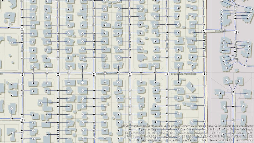
But how can we visualize the digitized direction of a line? The simplest way is to visualize the digitized direction of our lines using arrowheads.
After upgrading to utility network version 7, all lines have a ‘FLOWDIRECTION’ value of ‘With digitized’. Using a unique value renderer for the ‘FLOWDIRECTION’ attribute, we can easily visualize which way resources will flow in our network.

The direction the arrowhead is facing corresponds with the direction a line was originally digitized in. We can simply follow the direction of the arrow!

As a part of our analysis, we have identified a manhole that is blocked because of a small obstruction. We need to run an upstream trace to find customers impacted by this blockage. Now it is time to place a starting point on the manhole and run our trace!

We are provided with a selection set containing all features upstream of the starting point we placed.
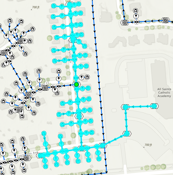
To better understand how to trace with digitized direction, let’s look at one part of the trace result selection set. When tracing using digitized direction, an upstream trace will follow the flow of the resource using the ‘FLOWDIRECTION’ network attribute to determine whether it should proceed. Conversely, a ‘Downstream’ trace facilitates tracing against the flow of the resource, again using the ‘FLOWDIRECTION’ network attribute.
In the above example, you notice a certain line is not included in the upstream trace results as expected. After reviewing the feature, you determine it has been digitized incorrectly and is being excluded from the trace.
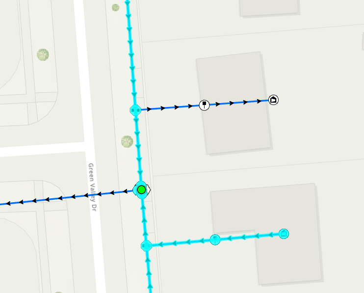
If we want to include these edges, we can simply modify the ‘FLOWDIRECTION’ network attribute in the Attribute Pane to ‘Against digitized’, run ‘Validate Network Topology’ on the dirty areas, and it will now be included in our trace results.
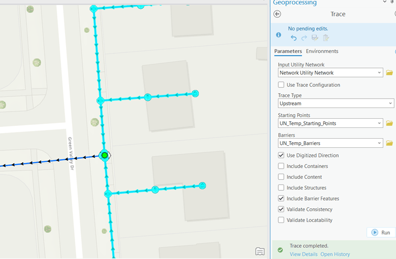
Using this trace, you have learned how to identify all the customers upstream of a manhole in a utility network using the digitized direction of lines.
Preparing Your Utility Network & Flow Direction Basics
The ability to trace using the digitized direction is a new, opt-in, capability within the utility network version 7 that adds additional functionality to ‘Upstream’ and ‘Downstream’ traces. Many users prefer to trace using source or sink based networks and there is no change in behavior to these trace types because of moving to utility network version 7.
To start tracing using digitized direction, you will need ArcGIS Pro 3.3 and ArcGIS Enterprise 11.3, if working with feature services. To enable tracing and management of flow network attributes within the line feature and object classes, you will also need to upgrade your utility network version to 7.
Once your utility network is upgraded, you will immediately notice several changes to your data and trace configuration options.
First, the line feature class and edge object class will now have a field called ‘FLOWDIRECTION’. This field contains a value that represents how tracing should interpret the digitized direction of the line. There are three possible domain values:
| Flow Direction | Description |
| ‘With digitized’
|
Resources will flow from the first vertex of the line to the last vertex of the line. |
| ‘Against digitized’
|
Resources will flow from the last vertex of the line to the first vertex of the line. |
| ‘Indeterminate’
|
Resources may flow freely in either direction through this line. |
Upon completion of the upgrade, all values in this field are set to ‘With digitized’ by default. You can modify values within this field using the Attribute Pane in ArcGIS Pro.
If the network topology is enabled, modifying the ‘FLOWDIRECTION’ network attribute will create a dirty area. You will need to run ‘Validate Network Topology’ to resolve the dirty area and update the network topology.

Second, the trace geoprocessing tool will now have an additional checkbox to “Use Digitized Direction” that appears when you select an ‘Upstream’ or ‘Downstream’ trace. This option is not active by default, but when selected will allow you to opt into tracing with digitized direction. Because tracing using digitized direction will ignore any subnetwork controllers you have defined, the ‘Domain Network’, ‘Tier’, and ‘Target Tier’ disappear when this option is selected.

Taking the Next Steps with ArcGIS Pro 3.3 and Enterprise 11.3
In this blog you have learned how to prepare your utility network to take be able to trace with digitized direction, gained an understanding of some of the changes utility network version 7 brings, and seen how to perform an upstream trace with digitized direction. This capability allows you to quickly and easily leverage your data to understand resource flow within your network.
ArcGIS Pro 3.3 and ArcGIS Enterprise 11.3 contain many improvements and new features for utilities. We encourage you to check out the ‘What’s new with the ArcGIS Utility Network at ArcGIS Pro 3.3’ blog and our many other blogs demonstrating the power of the utility network within a modern utility. If you have any questions about this functionality or the utility network, we recommend you continue the conversation over on the ArcGIS Utility Network community page.


Commenting is not enabled for this article.