By: Nathan Shephard (ArcGIS Pro Development team)
You may have heard of “procedural symbols” or “procedural content”, where a simple geometry (like a polygon) is converted into a more-complex shape (like a 17th-century Parisian building) using a formula based on rules and patterns. In the Esri universe, procedural rules are commonly written and consumed in CityEngine to quickly create rule-based urban landscapes.
What you may not know is that these rules can also be packaged and used in ArcGIS Pro in two ways: [1] to generate data via geoprocessing tools, and [2] as highly-configurable feature symbols.
ArcGIS Pro takes advantage of that second option and ships with several procedural symbols as part of the core style – you can discover them by searching the All styles gallery using ‘procedural’ as the keyword. The results will vary based on the layer type being symbolized – see Figure 1, below, for the supported types.
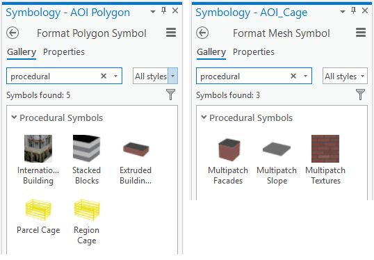
Notice how there are two “Cage” symbol options for polygons features. These two polygon symbols happen to reference the same rule package but have different default cage heights. The Parcel Cage symbol is better suited for a small parcel of land, while the Region Cage symbol is suited for larger areas, such as a mining site. Once the symbol has been applied, both options expose the same set of properties for adjusting the symbol further, such as using negative values for “depth” or changing the number of cage levels to “4” instead of “5”.
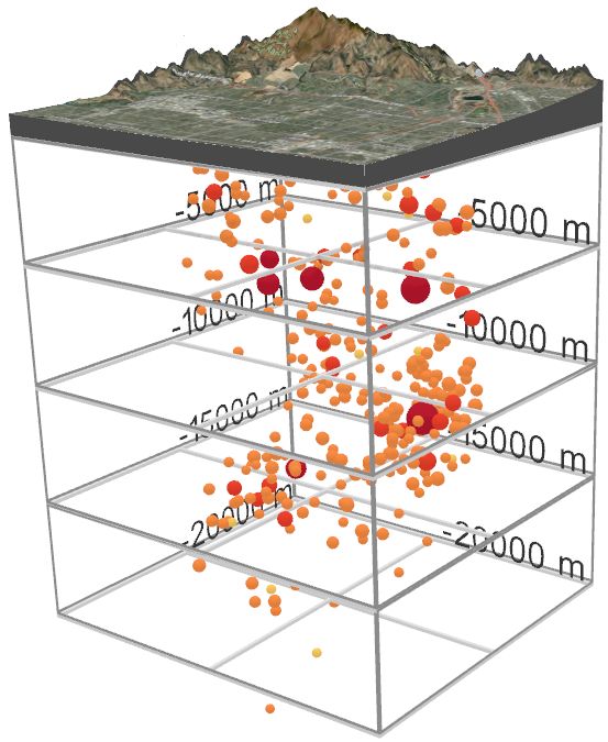
The cage symbol is one of the more advanced procedural symbol examples included in ArcGIS Pro, with many properties available for you to experiment with. There are so many options, in fact, we figured we should write a blog post about it…
Cage symbol – source data
The main purpose of cage symbology in a scene is to provide a vertical reference grid around an area-of-interest to help users better understand the elevation of features within it. Those features might be earthquake depths, or the heights of a proposed building, or even non-physical values such as the relative population of cities in a thematically-extruded scene, or the sequence of years in a space-time-cube – the procedurally generated cage symbol provides great flexibility in which values are shown.
To use the cage symbol for one of these examples, you must have a polygon feature layer. That layer must be in the 3D category of the Contents pane for the scene – that is, it has to be rendering as a 3D vector layer, not as a draped 2D layer. The polygon features themselves can be 2D or 3D, and the cage will use the elevation properties of the layer to set the base height of the cage. For example, a 2D polygon feature might use an attribute field to define its elevation, while a 3D polygon feature might use their embedded z-values as absolute heights.
The base of the cage must be horizontal-and-planar, so any polygons that don’t fit this bill – for example, a 3D polygon with a variety of z-values – will simply use the minimum z-value for the polygon for all vertices. While a rectangle shape is traditional for constructing cage symbols, the symbol will work with any shape polygon (though it is recommended you keep a low total number of vertices).
Once you have your polygons in the right location (horizontally and vertically), you can choose either the Parcel Cage symbol or the Region Cage symbol from the gallery and it will display as a 3D cage in the view. While it is possible the default settings will look good for your data, it is much more likely you will need to adjust the symbol to better suit your scene.
The configuration of the cage symbol is broken up into 5 parts:
- Core cage properties
- Optional advanced cage properties
- Optional bar labeling
- Optional cage title text
- Optional crossbeams
[1] Core cage properties
These properties must be defined for the cage to render in the 3D view.
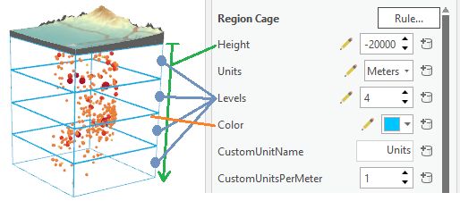
First, the cage needs to have a physical height (with associated z-units) – for example, 2,000 meters. When defining the units, you can select one of the four predefined units, or you can choose the “Custom (unit) set below” option and specify the name and meters-per-unit value of the custom units further down in the section. Negative height values will create a cage that expands vertically downwards (ie: into the ground).
The cage also needs to know how many vertical sections it is broken into – for example, 4 levels. The combination of height and number of levels defines how tall each section is. So, using our example values, the height of each level would be auto-calculated to 2,000 / 4, or 500m.
And lastly, the cage needs a color. You should choose one that works well based on the background of the scene. For example, yellow works well with a black background and dark basemaps, and gray works well with a white background and light basemaps, but you can use any color you like.
[2] Advanced cage properties
Next, you can choose to apply more advanced display options for the cage. You should only make changes in this section when you are unhappy with the default values.
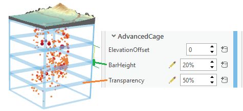
One of the options is to apply a vertical offset to the cage. This will move it up or down from the feature’s base height, and provides flexibility if your polygons are 2D and you don’t want to edit the data to move the symbolized cage to the required height.
You can also change the symbology of the exterior bars. The height, or thickness, of the bar is defined as a percentage of each section – so a 5% height value for a 40m section would create an exterior section line that is 2m high. You can also set the percentage transparency of the bars so the content being shown inside the cage is more clearly visible.
[3] Bar-labeling properties
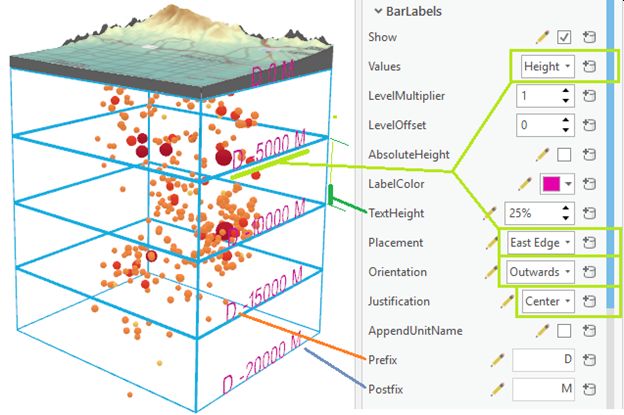
Labels tell the user what the cage lines mean. Given that you are adding the cage symbol to provide a reference grid for other content in the scene, they are a critical element to get right. Experimenting with the appearance of the bar-labels is recommended.
First, you can choose to display, or hide, labels for the section bars. This setting will be on most of the time.
For bar-label values, you have two options – either use the physical position of each of the sections (eg: 40m, 80m, 120m, etc) or the level number (eg: 1, 2, 3, etc). When using the physical values, check on the ‘AbsoluteHeight’ option only if you want the cage vertical offset, from section 2 (above), to be included in the displayed height value. If you are using the level number, you can apply an offset (eg: +100) and/or a multiplier (eg: *3) to the values that get displayed. One of these two options should allow you to get the “right” numeric values shown for each section in the cage.
For bar-label symbology, you can set the color of the text separately to the color of the cage itself, which allows you to apply contrast between the two items. You can also change the size of the text, which – just like for bar thickness – is defined as a percentage of the level’s height. Note that the labels on the cage are procedurally-generated geometries, so unfortunately this means you cannot choose a font.
Other bar-label symbology options include the label’s placement, orientation, and justification. As a quick tip, if you expect the scene’s camera to be more often outside the cage, choose the “Outwards” orientation for the text, and if the camera is more often inside the cage, choose “Inwards”.
For extending the bar-label text options, you can choose to append the vertical unit name to the displayed numeric value, or enter additional prefix and/or postfix text. The amount of text you can use as a bar label is very dependent upon the size and extent of your cage polygon feature.
[4] Cage title text
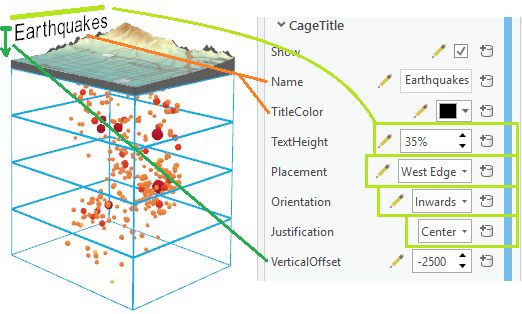
Sometimes it can be helpful to add a title for the cage as a way of further explaining what the axes represent, or what data is contained within it. The advantage of using the cage symbology to do this is that the text displays as a real-world sized object that is tightly bound and aligned to the physical cage.
The cage symbol allows you to enable the title element, type in the text to display, and then control the color, size, position, orientation, justification, and vertical offset of it.
[5] Crossbeam properties
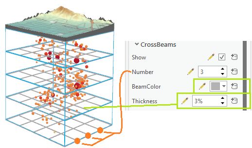
The final configurable section of the control relates to adding crossbeams. This part of the symbol can help align features that are in the center of the cage to the bar-labels at the edge of the cage.
The cage symbol allows you to enable crossbeams, specify the number of them to add per level, and set their color and thickness. Crossbeams are auto-calculated across the shape and will work best when used with regular shapes, like rectangles.
Summary
As you can see, the procedural cage symbol in ArcGIS Pro has many options for converting simple polygon feature into symbolized cages with multiple levels, labels, crossbeams, and a title. It is designed to be used in a wide variety of industries, from scientific analysis to mining to urban planning and so on, and – now that you know it exists – we hope it can help you create 3D scenes that communicate your data better. Some of you may even be inspired to write your own procedural symbols in CityEngine and use them in Pro.
I hope you found this information helpful. Best of luck with your 3D endeavors!
-Nathan.
ArcGIS Pro Development Team
PS: A few bonus tips for the cage symbol are included below. 😊
—- Bonus section ———————————————————————–
ADVANCED TIP 1: Connecting feature attributes…
If you have multiple cages in the same view, an option to consider is connecting one or more of the cage symbol’s properties to feature attributes or an Arcade expression. This allows you to digitize in several polygons and display them as cages with different heights, number-of-levels, vertical offsets, crossbeam counts, bar-label text, title text, (etc), all within a single polygon layer with the same symbol.
To vary the cage symbology using a feature attribute or Arcade expression, click on the database icon next to the applicable property and fill in the attribute mapping properties.

ADVANCED TIP 2: Show labels only on ‘the far side’ or ‘near side’ of the cage…
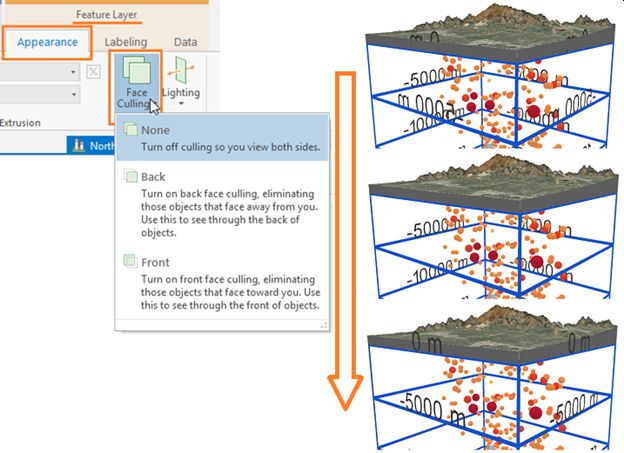
ArcGIS Pro allows you to specify face-culling for a 3D layer, which will hide parts of a 3D object based on the direction the geometry was created to face. For the cage symbol, the “inwards” and “outwards” text elements are generated with a direction in mind, so you can take advantage of this layer rendering property to only show some of the text as the camera zooms around the scene.
To enable back-face or front-face culling for a layer, select it in the table of contents and, on the Feature Layer contextual ribbon tab, choose a culling option from the Face Culling drop-down gallery. With a culling option of ‘None’ for outward-facing text, all four sides will show the text. With the face-culling option set to ‘Back’, the text labels on the far side of the cage will be culled from view.
ADVANCED TIP 3: Sharing cage symbols in a web scene…
While an effectively-symbolized scene in ArcGIS Pro is helpful for many scenarios – including sharing images and videos – you might want to also include this symbol in an interactive web scene. Unfortunately, the web scene does not natively support procedural symbology, so you will need to convert the cage symbol into a 3D object before publishing to the web.
Use the ‘Layer 3D to Feature Class’ GP tool to convert the symbolized cage layer into a fixed 3D object in a new multipatch feature class. Double-check your symbology before doing this because the cage will no longer be configurable afterwards. Then simply remove the symbolized polygon layer from your scene, and publish.

Article Discussion: