At User Conference 2018, Madeline Schueren, from the Esri Geodesign team, showed some of the new 3D editing features in ArcGIS Pro 2.2. In her demo, she showcased how to create and edit in 2D and 3D to quickly model data and make decisions.
In her demo, Madeline introduced a plan of the new Redlands Packinghouse District. This up-and-coming shopping center showcases both many of the problems that city planners face today as well as some of the innovative solutions.
Madeline’s web scene of the Packinghouse District is here for you to explore, but you can also create your own.
Explore the web scene below.
Redlands Redevelopment- Packinghouse District
Step 1- Extrude 3D features
1. Download the Redlands_Redevelopment zip file and unzip it.
The folder contains an ArcGIS Pro project titled Redlands_Redevelopment.arpx and a folder of images, along with other data.
2. Double-click Redlands_Redevelopment. If prompted, sign in to your ArcGIS organizational account.
Note: If you don’t have an account, get a free trial.
ArcGIS Pro opens to a 3D scene showing the new Packinghouse District in Redlands. Recently, a restaurant was added, and to show it off, you want to add real-life texture to it.
3. On the ribbon, click the Edit tab. In the Selection group, click Select and click the Footprint polygon on the map.
Note: to move the map while in Edit mode, press the C key while panning the map. To change the angle of the map, press the V or B keys while panning.
The building footprint has already been created as a 2D feature. You’ll extrude it to show height.
4. Copy the feature (use Ctrl+C or the Copy button on the Edit tab), then on the ribbon in the Clipboard group, expand Paste and click Paste Special.

5. In the Paste Special window, select New Building and click OK.
6. On the ribbon in the Tools group, click Vertices. If necessary, click the new building feature on the map to select it.
7. On the status bar at the bottom of the screen, click the second button to the right of the elevation bar to turn on Dynamic Constraints.

This tool tells you how high you’re extruding a feature as you move it.
8. Hover over the feature and click the green circle. Drag the feature up from ground level until it’s about 20 feet off the ground.
Tip: You can also press the Tab key while dragging the feature and enter the exact height you want.
9. When you’re satisfied with the feature height, click the box with the green check to finish editing.

10. On the ribbon in the Manage Edits group, click Save, then click Yes to save all edits.
Step 2- Add texture
1. On the ribbon, click the Map tab. In the Navigate group, click Bookmarks and choose Front Side.
2. Click the Edit tab, expand the Tools list and click Multipatch Texture.
3. If necessary, click the new building to select it.
The building face highlighted in red is the one you’ll be adding texture to.
4. In the Modify Features pane, under the selection, click Texture, then click Load Texture and navigate to the Images folder in the data you downloaded.
5. Choose Front.jpg and click Open, then click the side of the building facing the parking lot.
The image is applied to the front of the building, but is not positioned properly.
6. In the Modify Features pane, zoom out and position the image to fit the scale of the building.
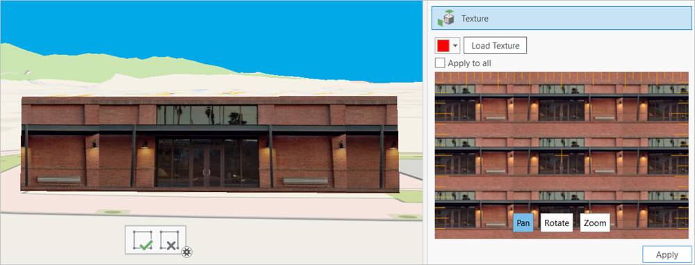
Note: The feature shown in the Texture pane may have to be zoomed out. The image repeats to fill the box.
7. When you’re satisfied with the positioning, click Apply.
8. Repeat the process for the three sides of the building using Side.jpg. Click to Apply, then the green check to finish editing after each side.
9. Add the roof using the same process as with the sides. When you’re satisfied, on the ribbon, in the Manage Edits group, click Save.

Step 3- Add Depth
Based on the shadows on the roof, you can see that these skylights should be raised up from the roof. They are, in fact, angled to face north.
1. On the ribbon, in the Tools group, click Vertices.
2. Click to select the new building feature, then click Edit Vertices.
Once you select the feature, it may disappear briefly while the features load.
3. Draw a rectangle around the perimeter of one of the skylights. Once it is selected, hover over the center and drag the green dot up to extrude it to about 3 ft.
4. Hover over the long edge of the skylight opposite the shadows until you see the green dot and drag it back down to the level of the building.
Tip: Use the keyboard shortcuts, press the C key to pan the map and the V key to tilt it.
5. At the bottom of the map pane, click the box with the green check to finish editing.
6. Repeat the process for the other four skylights.

7. Once you’re happy with your edits, on the ribbon in the Manage Edits group, click Save.
You now have a model of the building that is similar to the others in the complex. To fully leverage it, you can perform a viewshed analysis, like Madeline did onstage at the Plenary session. You can also share it as a web scene layer, like the one at the beginning of the blog post.
For more information about building web scenes, check out Get Started with Scene Viewer at Learn ArcGIS. For more workflows using 3D data in ArcGIS Pro, try Estimate Storage Capacity with Drone Imagery or Fly Through South America in a 3D Animation.
If you liked Madeline’s presentation, check out her Schiedam Web Scene demo from the 2018 Federal User Conference.

Commenting is not enabled for this article.