In a previous post I talked about techniques for establishing real world coordinates inside Revit using Autodesk’s Revit software and an Esri coordinate system definition file (PRJ). If you DON’T have access to Revit software to update the coordinates of your Revit file you can use the georeferencing tools found on the Manage Tab of the Revit Building Data ribbon in ArcGIS Pro. And even if I do have access to Revit I may not be allowed to, or I may not want to modify the coordinates of the Revit model, but instead may want, or need to perform the georeferencing on my own in ArcGIS, independent of the Revit BIM workflow.
The georeferencing tools in ArcGIS Pro allow me to create a coordinate transformation file that ArcGIS Pro will read and use to apply the appropriate offsets each time a CAD or a Revit file is opened in ArcGIS Pro. This transformation (WLD3) file is simply an ascii file containing three sets of to and from points that define a 3D coordinate transformation. A collection of geoferencing tools are provided to help me generate this file. The tools can be applied in combination to help me locate my data properly.
This is the ArcGIS Pro Georeferencing workflow I use for Revit files. (A video using these steps follows at the bottom)
- Since I am working with 3D BIM data I work in 3D, so I will use a brand new ArcGIS Pro local scene to do my georeferencing work.
- I often need to view underground for subtle adjustments that may be at ground level or below. (I use the appearance tab with the Ground layer in the TOC and check the Navigate Underground option ON).
- I will search for and execute the DEFINE PROJECTION geoprocessing tool from the toolbox on the Pro Analysis tab of the ribbon.
- I will browse to one of the feature layers of my Revit file, such as the FLOORS in the Architectural discipline dataset of the RVT file on disk. I will select the Revit category that will best assist me in locating my model on the map. The ExternalShell is also often a good alternative, or sometimes like I show in my video the LocationPoints may be all you need. The LocationPoints include the Revit Project Base Point, and Survey Base Point and their attributes such as the stored coordinates and any rotation to north values. These may or may not contain any useful information. (In the attached video one of my example uses these points exclusively.)
- I then choose the Esri coordinates system definition that should match my data. This step is REQUIRED. I must select a PRJ file that is suitable for my data and the units of the coordinates in the definition MUST the display units I have set in the Revit model – either Imperial or Metric. Because the units of a Revit model are NEVER drawn in Latitude and Longitude I will NEVER be selecting a global coordinate system definition (PRJ) to associate with my Revit model. This can be different than the coordinate definition of the ArcGIS Scene and other data in that scene.
NOTE: If your Revit model is metric (Meters, cm, mm, etc…) the linear units of your coordinate system definition in the PRJ file MUST be METERS. If the display units in the Revit Model are feet or inches, similarly the units of the coordinate system definition MUST be feet. The linear units of the PRJ file will indicate to ArcGIS how to properly handle the coordinates stored in the Revit model either Imperial or Metric.
- The default in ArcGIS Pro’s Geoprocessing options is to add data to the scene after running a geoprocessing tool like DEFINE PROJECTION. If you don’t have this option set you would add your Revit category layer to the scene now, either dragging and dropping from the catalog window or using ADD DATA on the Map tab of the Ribbon.
- To focus my work I will only include the information in my scene that helps me georeference my data. If I have geometry I will be needing to snap to, I will add just enough data to get my job done. And I like to do it after the scene’s coordinates have already been defined in case this extra data might establish a coordinate system in the scene that might not match what I want for my Revit data. Adding to the scene after my Revit data ensure this data is projected to the scene’s coordinate system rather than defining the scene’s coordinate system.
- Next, I ZOOM to the location in the ArcGIS Pro scene where I know the building belongs.
Tip: If I know the building’s street address I might use the LOCATE button from the MAP tab of the ArcGIS Ribbon to help me locate that address in my scene.
- Creating a bookmark to your building location is a good way to easily return to the site.
- If my Revit model has the correct coordinates defined already in the Revit file itself, and I have the proper PRJ file, I will see my data display properly in the scene and I can STOP HERE and perhaps all I needed was to define the coordinate system the Revit file author used. If not, I will continue to georeference the data…
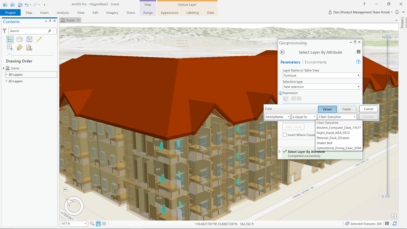
- (Optional) I may want to pre-select the features from the Revit layer that will best assist me in the location of my building (like the FLOORS or ExteriorShell) using one of the feature selection methods in ArcGIS Pro on the layer I will be using for as the feedback sketch for the georeferencing tool.
Note: If I don’t pre-select features from the layer I will use for the purpose of georeferencing, the georeferencing tool will automatically select the first 1000 feature of the feature layer I have highlighted in the TOC as a feedback sketch during the georeferencing process. If I select more than 1000 features, I will see all the selected features in my sketch, but I may find the performance is not optimal. If I am ok with the 1000 features or there are less than 1000 feature in my feature class I can skip the step of pre-selecting.
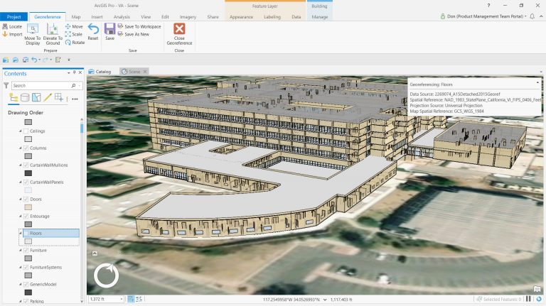
- I invoke the GEOREFERENCE tool on the Manage Tab of the Building context menu in ArcGIS Pro.
- If I have zoomed away I will zoom back to the expected location of my building, using my bookmark or some other technique such as typing in the building’s address in the ArcGIS Pro Locate I have selected the Revit layer in the TOC that will best help me locate the model in the Scene.
- I use the MOVE TO DISPLAY tool to move the georeferencing graphic feedback I selected into view.
- I may not always have all the data to make precise re-positioning of my Revit data, but when I do, I will want to be sure to set the SNAPPING setting before I georeference my data with the georeferencing MOVE and ROTATE tools.
- I use the MOVE, ELEVATE TO GROUND and ROTATE tool on the GEOREFERENCING ribbon to nudge and or snap the position of the building in place.
Suggestion: I may want to modify my view angle to use the MOVE tool in the vertical to place the bottom stair step on the ground or the bottom of a ground level door. For this reason, earlier I made sure to allow navigation underground of my scene. I might also want to review the software help for the ArcGIS editing tools to familiarize myself with the behaviors of these editing controls.
Tip: To perform dynamic panning and zooming I press the [Z] key on my keyboard while using the mouse wheel/buttons to navigate in 3D at any time, even when other tools are active.
- I use [CTRL]-click to re-position the anchor point of the MOVE, ELEVATE TO GROUND or ROTATE widget to make precise adjustments. This action also supports snapping. Starting in ArcGIS Pro 2.3 the ELEVATE TO GROUND tool will also honor the anchor point to move the model vertically from that anchor point, raising or lowering the entire model until the anchor point is on the ground at its current location in X,Y.
Note: If the angle to true North was set correctly on the Revit Project Base Point (and it often is even when the coordinates are not set) I should not have to ROTATE the Revit model while georeferencing. Since Revit models are always drawn to scale I should NEVER have to use the SCALE tool. I might only use the scale tool if I am working with some non-building object drawn in Revit for which I want to make a copy at varied sizes.
- Once satisfied with the 3D position I can save the georeferencing session and a 3D World File (WLD3) will be generated on disk that is named according to the name of the <Revit File Name>.WLD3. The WLD3 file is a new ancillary file to store the 3D coordinate transformations for CAD or Revit data.
Note: If you have a directory full of Revit models that all share the same “relative” coordinates and are positioned correctly one relative to the other, you can rename a valid WLD3 file to “ESRI_CAD.wld3” and all of the Revit Models will be repositioned according to the offset defined in that ESRI_CAD.WLD3 file. The SAVE TO WORKSPACE tool on the GEOREFERENCING toolbar will save the current combination of WLD3 and PRJ files to the special ESRI_CAD.WLD and ESRI_CAD.PRJ universal files. You would NOT want to use these files unless your other Revit models are positioned relative to this one. If each stands on its own with a unique origin the models could all just stack up upon themselves. The ESRI_CAD.WLD3 and ESRI_CAD.PRJ are useful when models are relative one to another but still need to be georeferenced.
I can now add this Revit data to any other scenes and ArcGIS Pro will position the data correctly in those scenes no matter what their coordinate systems may be set to because I have selected and stored valid PRJ and WLD3 files for my Revit file.
Watch this video Example of Georeferencing Revit Models in ArcGIS Pro 2.3.


Commenting is not enabled for this article.