The Call Comes In
Quickly and accurately map emergency incidents with a composite address locator
By Mike Price, Entrada, San Juan, Inc.
| |
What You Will Need
- ArcGIS Desktop 9.3 (ArcView, ArcEditor, or ArcInfo)
- Sample dataset downloaded
|
|
This article as a PDF .
Address geocoding is an essential public safety skill. However, officers need to understand the benefits, limitations, and complexities of systematic address locators. To quickly and accurately map incident locations, a Public Safety Access Point (PSAP) relies on computer-aided dispatch (CAD) software and georeferencing datasets to match the caller's address to a point on the map. At the dispatch center, a trained operator must capture, interpret, record, and map as much incident information as possible.
After determining the incident's location, the operator identifies the needed and available resources and passes as much information as possible to responding units. These tasks must be accomplished as quickly as possible—typically 60 seconds or less. Once mapped, the CAD system matches the closest available emergency resources with the call type and sends out automated tones, coupled with digital information and voice instructions. Consistent, complete, and current addressing datasets are essential to this process.
This exercise shows how to produce addressing datasets by creating geocoding services or address locators for three datasets that will place a location on a map with a high degree of accuracy. Rather than geocoding a single incident, this exercise processes several thousand incident points captured during a single year in a major metropolitan area. Standardizing addresses and using a progressive composite address locator will achieve an extremely high success rate on the very first pass. This exercise applies the same sequential logic that is used by response centers around the world.
The data for this exercise was created for a textbook and tutorial series on performing emergency services mapping. It is based on data from actual jurisdictions and represents field conditions but has been modified to protect sensitive information.
The exercise is organized into five tasks.
Getting Started
 |
| The exercise data is based on data from actual jurisdictions and represents field conditions but has been modified to protect sensitive information. |
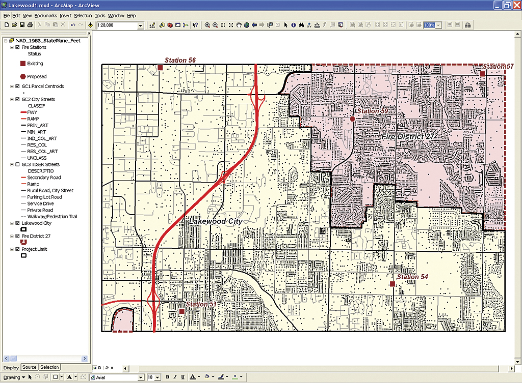
To get started, download Lakewood.zip. Store this file near a root directory and extract the data, respecting directory structure. Start ArcMap, navigate to the new Lakewood folder, and open Lakewood1. Right-click in an open toolbar area and select the Geocoding toolbar. Move it next to the other open toolbars and inspect its buttons. The Address Locator Manager and Geocode Addresses buttons are active. Two other tools, Location Inspector and Review/Rematch Addresses, are inactive.
Task 1: Understanding Addressing Data
A typical PSAP will use several address datasets to place an incident on a map. A geocoding sequence starts with the most reliable, accurate, and current dataset available to identify a single point location on a map. To increase the success rate of the geocoding process, the service will standardize incoming addresses to match the reference data schema. Place-name alias tables also increase geocoding reliability.
- Open the attribute table for GC1 Parcel Centroids and inspect its fields. Study the SITE_FULL field and sort it. Notice that each address includes one standardized string, possibly including an address numeric; a direction prefix, a street name, a street type, and a direction suffix. These address points provide a certain address match against standardized input data with a high degree of reliability.
- Open the attribute table for GC2 City Streets and inspect its fields. This dataset, developed and maintained by the Lakewood Public Works Department, is current and complete. This polyline dataset separates addressing into left and right and to and from numerics, and includes separate fields for name direction and type. GC2 City Streets is the second geocoding data source. It supports a U.S. Streets Locator. Unfortunately, CAD data often does not include sufficient information to apply a U.S. Streets with Zone Locator. Typically this data lacks municipality or ZIP Code information. Each agency must decide how to clip streets to include unique names or process addresses in different communities that share similar street names.
- Next, open the attribute table for the GC3 TIGER Street shapefile and inspect its fields. This dataset is adapted from 2009 Census TIGER street data, now in development by the U.S. Census Bureau. It includes a schema similar to the Lakewood Public Works data. Notice that field names and placement are different. This is the third addressing dataset, and it captures many road intersection addresses and the locations of incidents that might occur outside the extent of the Public Works dataset. The TIGER 2010 data, not yet released, will be different from TIGER 2000 data.
- Now click the Add Data button, navigate to \Lakewood\DBFFiles and locate Inc_2008_Address, and load this table containing incident data. Open this table and inspect it. This dataset contains nearly 7,000 incident records and has only a few fields. It has an index field (INDEX), an incident number field stored as an alpha string (INC_NO), and a standardized address field named (ADDRESS2). Notice that there is no field in this dataset to identify a geocoding zone.
- Sort ADDRESS2 and notice it contains both numeric and street intersection addresses. These addresses were generated and posted using CAD software, then edited by the local jurisdiction to correct inconsistencies. This data is clean and contains only incident addresses. Other information will be joined to these geocoded points later using the INC_NO field.
To review: In this task, the three reference datasets in the map document were reviewed, and one file containing incident data was added to the map document.
 |
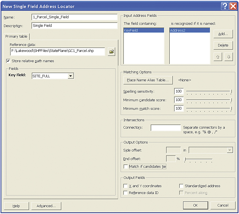
| Create a Single Field Address Locator that references the GC1_Parcel shapefile. |
 |
| The second geocoding data source, GC2 City Streets, supports a U.S. Streets Locator. It is maintained by the Lakewood Public Works Department and is current and complete. It will be used to build the 2_City_US_Streets address locator. |
 |
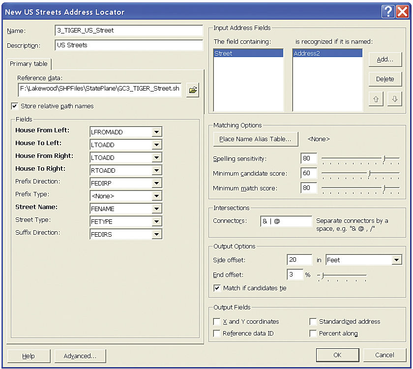
| The data source for the third address locator, the GC3 TIGER Street shapefile, was adapted from 2009 Census TIGER street data, now in development by the U.S. Census Bureau. |
 |
| Use the three individual address locators to create a composite address locator. |
Task 2: Creating Individual Address Locators
Address locators will be created for each reference dataset in this task.
- Save the ArcMap document, close ArcMap, and start ArcCatalog. Navigate to \Lakewood\SHPFiles\StatePlane and preview the tables and geography for the shapefiles. The file name for each reference file begins with the letters GC and a numeric code that indicates that file's geocoding sequence.
- In the ArcCatalog tree, right-click the \Lakewood\SHPFiles\StatePlane folder and select New > Address Locator. Specify Single Field as the Address Locator Style and click OK.
- In the New Single Field Address Locator dialog box, enter 1_Parcel_Single_Field as the Address Locator name. On the Primary table tab, set Reference data to \GC1_Parcel.shp and set SITE_FULL as the Key Field. In the Input Address Fields area, delete Name from the field under is Recognized if it is named and add Address2. Set all scores and sensitivities to 100.
- Under Output options, uncheck the box next to Match if candidates tie. It is essential to uncheck this box because all ties (based on duplicate addresses) will be bumped to the City Streets locator. Click OK to build the 1_Parcel_Single_Field locator.
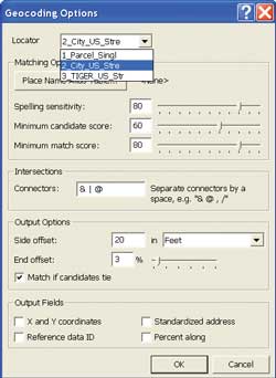
- Build the 2_City_US_Streets geocoding service by right-clicking the \Lakewood\SHPFiles\StatePlane folder and creating a second address locator. Use Tables 1 and 2 as guides when creating this locator. Name this address locator 2_City_US_Streets. Set \GC2_City_Street.shp as the reference set, and define reference fields using the same parameters as 1_Parcel_Single_Field locator. This time, using the information in Table 1 , specify fields for numerics, direction, and type. Although many addresses will automatically match, don't forget to make sure STYPE is chosen for the Street Type field. If a required field is accidentally omitted when creating a locator, delete the locator and rebuild it. Set only Address2 as the recognized field and set spelling and scores to 80, 60, and 80. Accept the Connectors defaults and leave other choices unchanged. Click OK to build this locator.
- Next, build the 3_TIGER_US_Street geocoding service using parameters in Tables 1 and 2. This locator is similar to the 2_City_US_Streets locator. Because the new TIGER codes are not consistent with earlier systems, the field names will not assign automatically, so carefully assign fields as shown in Table 2 .
Task 3: Building a Composite Address Locator
The three individual address locators just created are now linked together in a composite address locator. A composite locator links two or more other address locators together in a hierarchical order and passes unmatched addresses from each locator to the next. This composite address locator will geocode using Parcel Centroids first, then City Streets, and finally TIGER Streets.
- Right-click the \Lakewood\SHPFiles\StatePlane folder and specify Composite Address Locator.
- Using Table 3 , name this locator Composite_Parcel_ Street_TIGER and add participating locators in order: 1_, 2_, and 3_. These numeric name prefixes will be useful soon.
- Once all three are loaded, perform the next step. It is a performance tip. On the right side of the New Composite Address Locator wizard, find the Input Address Fields area. Next to The field containing window, click the Add button and specify Address as the primary field. Set its recognized name to only Address2. By specifying only Address2, the composite address locator will target only standardized data and ignore other Address fields. Typically reference datasets can also contain a primitive Address field.
 | |  |
| Keep all Participating Address Locators checked and select each one and individually set its Input Mappings field to ADDRESS2. |
- Keep all Participating Address Locators checked; select each one and individually set its Input Mappings field to Address. Use any individual address locator to calculate the output spatial reference. After setting the spatial reference and all three Input Mappings, the OK button should become active. If it does not, review the setting. Click OK to build the composite address locator. Now it is time to geocode all 6,976 incidents. Close ArcCatalog and reopen the Lakewood map document in ArcMap.
Task 4: Geocoding Incidents
Now, after setting some parameters for the composite address locator, it will automatically geocode all the incidents.
- In ArcMap, load the Geocoding toolbar, if necessary, and click the Address Locator Manager button. Navigate to \Lakewood\SHPFiles\StatePlane and load only Composite_Parcel_Street_
TIGER. Close the Locator Manager window.
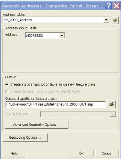
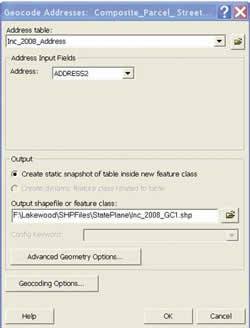
- Open the TOC Source tab, right-click the Inc_2008_Address table, and select Geocode Addresses.
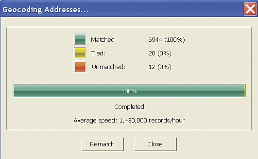
- Set the output file location and name to \Lakewood\SHPFiles\StatePlane\Inc_2008_GC1. Using a numeric counter in the file name will make it easier to rerun the model or test it with differing parameters. Click the Geocoding Options button to verify that all three individual locators participate in the composite address locator. Update or adjust properties, such as spelling sensitivities and threshold scores, at the same time if necessary. Click OK to continue and watch the geocoding process.
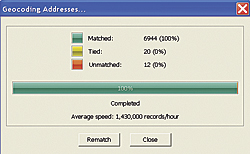 |
| The composite address locator should generate 20 ties and 12 unmatched addresses. |
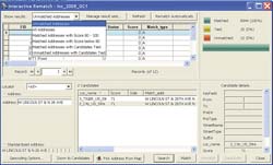 |
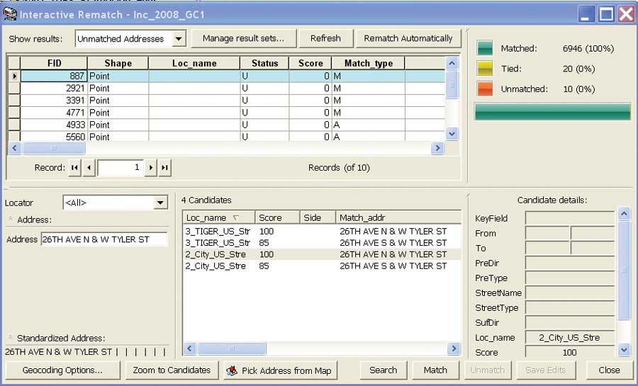
| Click the Rematch button and under Interactive Rematch, select Unmatched Addresses. |
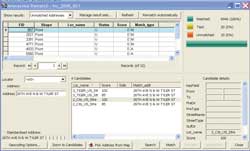 |
| Use the Fixes1 table to fix unmatched addresses by copying the ADDRESS2_F string into the text box next to Address on the left side of the Interactive Rematch dialog box. |
- If the three address locators were built according to the specifications given, they should generate a high percentage of matches. Only about 20 ties and 12 unmatched addresses should be left from the set of 6,976 incidents.
- The sample dataset includes a Microsoft Excel spreadsheet containing suggested fixes for known addressing errors. Navigate to
\Lakewood\Utility and load the Database worksheet, Fixes1.xls. Review its contents. In the real world, records management at a fire station is never perfect, and this spreadsheet contains fixes for several nongeocoded records.
- To update these unmatched or tied records, click the Rematch button. Let's repair unmatched addresses. Under Interactive Rematch, look at the Show results area and select Unmatched Addresses. In the results window, locate an improperly geocoded address and find its corresponding entry in the Fixes1 table. Copy the ADDRESS2_F string into the text box next to Address on the left side of the Interactive Rematch dialog box. Click the address in the Candidates list and select the record with the highest percentage (which will likely be the one with the highest order, e.g., 1_, 2_, or 3_) and click Match. The score will change from U to M, and the Loc_name field now lists reference data, providing the best fit. Continue down the list, making repairs, selecting the best reference data and building matches. When finished, all records should match.
- Review tied records next. In Show results, select Matched Addresses with Candidates Tied. Locate the ADDRESS2 window and sort its contents so identical tied addresses are grouped. Ties often occur in clusters, so fixing one will often fix others.
- Click one of the candidates in the window. The selected record is displayed as a larger yellow dot on the map. Below the Candidates window, click the Zoom to Candidates button. If you could access the actual incident records, you could select the appropriate point. However, that is not the case in this exercise, so select the westernmost or northernmost point (as long as these points are in close proximity—say, 1,000 feet or less). Click the Pick Address from Map button and use the crosshair tool to choose the best candidate, then click Match. Also check the Fixes1 spreadsheet to see if any ties show up there.
After matching the last tied records, all tied records should show a 100 percent score. While matching ties, look for the reasons they occurred. Some are readily fixed by editing street address ranges, which will require that you rebuild the affected address locators before continuing. Other errors, such as those caused by looped streets and offset intersections, are hard to avoid.
Finally, consider matched addresses that score less than 100. Show results for matched addresses and sort the Score field in ascending order. Only a few records will have scores less than 100. See if you can boost those scores to 100 by using observations, intuition, and the Fixes1 spreadsheet. After fixing all records, close the Interactive Rematch dialog box and save the map document.
Task 5: Adding Detailed Information about Incidents
The input data contains only incident numbers and addresses. With all these points properly placed on a map, joining or relating data from other tables will add more information on the incidents such as date and type of incident. The last step will symbolize incidents using a graduated color scheme that identifies incidents by type.
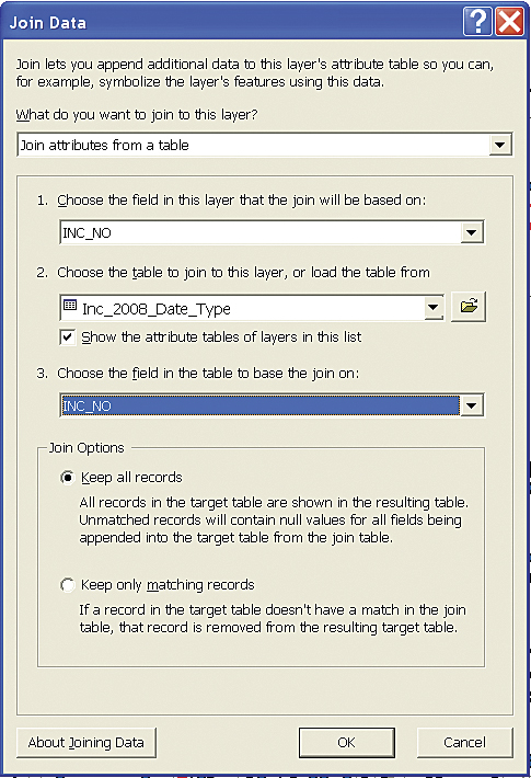
- Navigate to \Lakewood\DBFFiles and add Inc_2008_Date_Type.dbf to the map document. Open Inc_2008_Date_Type and compare it to the attribute table for Geocoding Results: Inc_2008_GC1. Note that these tables share a common field, INC_NO, so there may be a one-to-one relationship between the tables.
 |
|
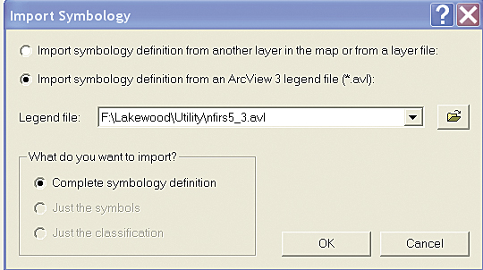
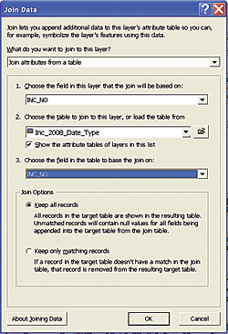
Join the table Inc_2008_Date_Type to Geocoding Results: Inc_2008_GC1 to symbolize the incidents. Load the ArcView 3.x legend to use the NFIRS color scheme.
|
- Right-click Geocoding Results: Inc_2008_GC1 and choose Join. Create this join to Inc_2008_Date_Type.dbf using INC_NO as the common field. Inspect the results and verify that all records have joined.
 |
| Once the incidents are symbolized, check the symbology properties to learn more about the incidents. |
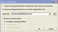
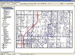
- The next step symbolizes incident points using a graduated color legend that corresponds to the National Fire Incident Reporting System (NFIRS). Open the Layer Properties dialog box for the incident layer (Geocoding Results: Inc_2008_GC1) and click the Symbology tab. Click the Import button and choose ArcView 3 (*.avl) file and navigate to the \Lakewood\Utility folder. Select nfirs5_3.avl and set the Value field to NFIRS_TYPE. Click OK several times to apply the legend.
- Save the finished project. Once the color scheme is applied, check the symbology properties to learn more about NFIRS incident types. Incidents are coded thus: 100 series points are fire related; 200 series points are explosions or ruptures; 300 series points are rescues and EMS calls; 40 series points are hazardous conditions; and all points over 499 are service calls, false alarms, and special calls.
Acknowledgments
The author thanks all the people who helped provide mapping data and other information that was used in this tutorial. Because this data has been synthesized, those providers might not recognize their own data. Thanks also go to the author's advanced GIS students at Bellingham Technical College in Washington who helped identify and resolve real-world training issues.
|