By Ken Field, Esri Research Cartographer
We received an interesting question on Ask a Cartographer recently which asked if there is a way to create overpasses when the underlying objects are polygons rather than lines. For those familiar with Cartographic Representations, the use of the Create Overpass tool is a great way of creating masks and parapets when one line feature crosses another, for instance where a road crosses a river or when one road class crosses another. In these situations, the use of a parapet is helpful to ensure that the map reader doesn’t infer there to be an intersection rather than an over- or underpass. Figure 1 shows how the tool works successfully for linear features. Applying good cartographic design in this way ensures the map reader can easily decipher that the vertical red line feature crosses over the underlying line features.
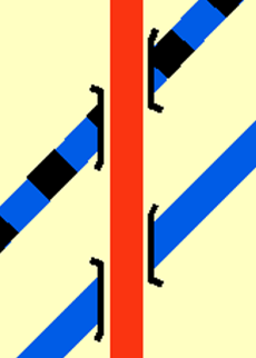
Figure 1. Result of using the Create Overpass tool to create parapets for linear features
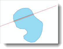
The Create Overpass tool does not, however, work when a line feature class crosses a polygon feature. There are potential situations in which a similar cartographic effect might be useful. For instance, a road (represented as a line feature) might cross a floodplain or a lake (both represented as polygon features) via a bridge. This blog entry provides a workflow, based on the Create Overpass tool, that you can use to create masks and parapets for lines that cross polygon features. Figure 2 shows an example in which this might be useful as a road crosses a lake. At first glance the linear road feature appears to run through the polygon lake but in reality the road crosses the lake on an elevated section of pavement. This geographic relationship between the road and the lake needs to be communicated effectively through more appropriate cartography.
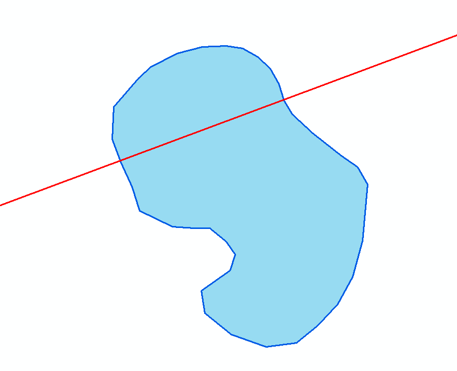
Figure 2. Example of a linear feature class crossing a polygon feature class in which a better cartographic solution is required
The process described here is dependent upon using Cartographic Representations so all data have to be in geodatabase format. First, you will need to convert any boundaries of the polygon feature (the lake, in our example) to a line feature class. This is done using the Feature to Line tool. You then convert the resulting line feature class symbology into a Cartographic Representation by right-clicking the layer in the Table of Contents and selecting “Convert Symbology to Representation”. You’ll get a line feature class for the boundary of the polygon, in our example, the lake in figure 3.
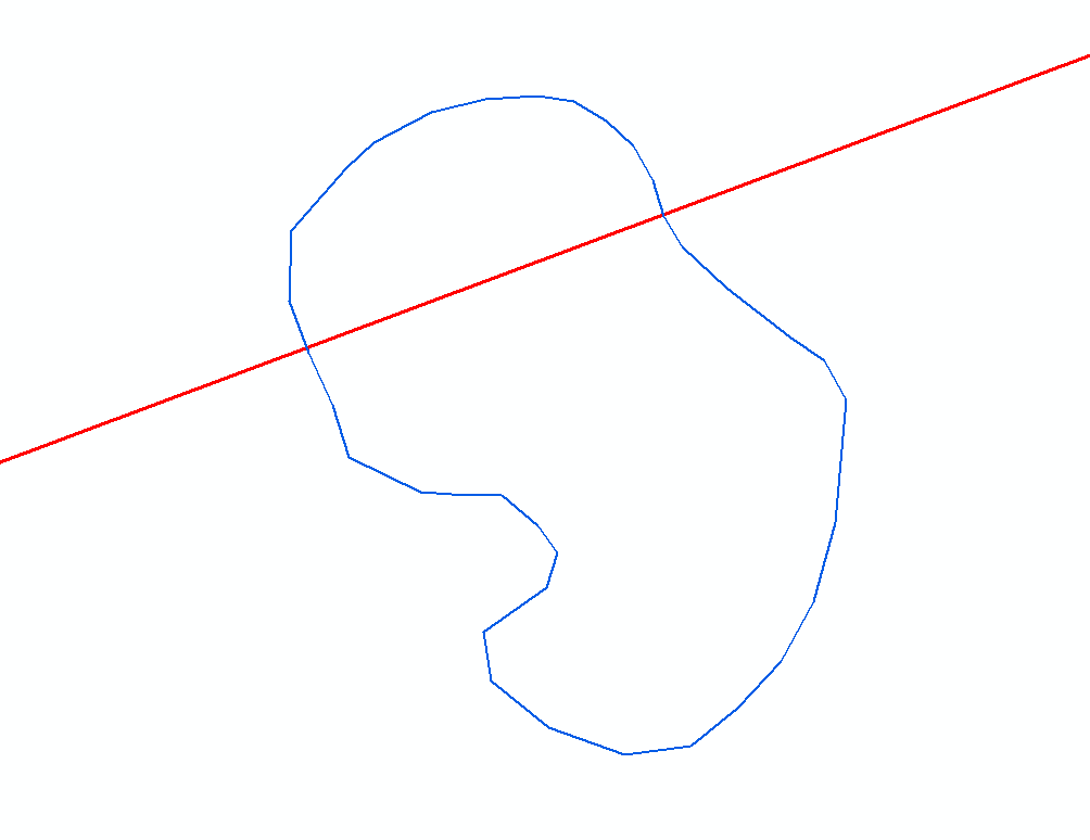
Figure 3. The lake boundary as a line feature class
You will also need to convert the line feature class (the road, in our example) to a Cartographic Representation so that you can use the Create Overpass tool in the Cartographic Refinement Toolset (figure 4).
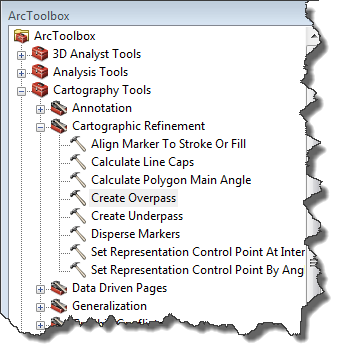
Figure 4. The Create Overpass tool in the Cartographic Refinement toolset of the Cartography Tools toolbox
This will create parapets and masks anywhere that the road features cut across the lines of the lake outline. Figure 5 shows the settings you can use when you use the tool, specifically the file names for the output feature class (over_FC) and the relationship feature class (over_RC), the name for the parapet symbology (bridge), and some settings to specify the length and width of the mask and the parapet symbology.
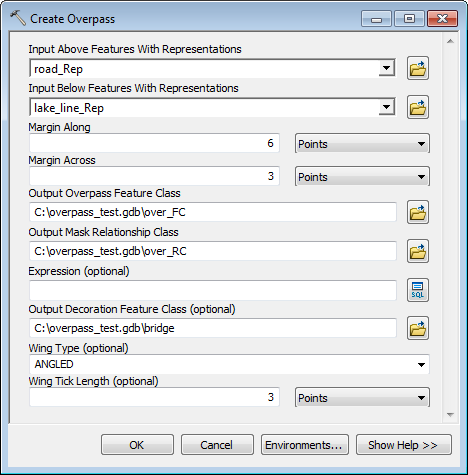
Figure 5. Using the Create Overpass tool
With this tool, you are effectively creating overpasses across the boundary lines of the polygon, and you will get one set where the road enters the polygon and another where it leaves the polygon, as figure 6 shows.
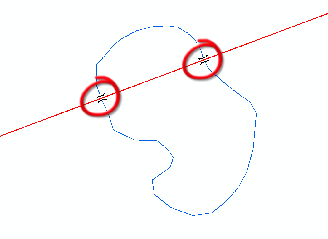
Figure 6. Result of applying the Create Overpass tool on the bridge and lake boundary features
Next, you’ll need to convert your new parapet (bridge) and mask (over_FC) feature classes to Cartographic Representations by again right-clicking the layers in the Table of Contents and selecting “Convert Symbology to Representation”. Do this for both feature classes remembering to check the “Change the Geometry of Supporting Features” in the Convert Symbology to Representations dialog box so that any future edits will be applied to the feature geometry directly rather than the symbology representation. Checking this option is an important step since it will assure that the masking will work properly at a later stage in the workflow. In this example, the two new feature classes are called bridge_Rep and over_FC_Rep (figure7).
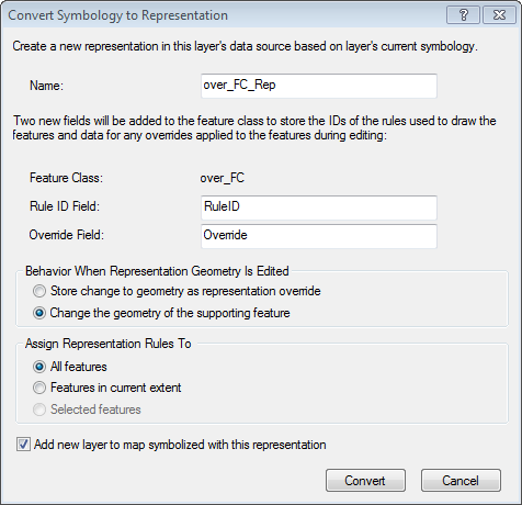
Figure 7. Converting the Overpass feature class to a Cartographic Representation
Both the bridge (bridge_Rep) and mask (over_FC_Rep) representation feature classes are multipart features, so in order to be able to edit them individually you now need to convert them each to singlepart feature classes using the Multipart to Singlepart tool in the Data Management > Features Toolset. This creates two new singlepart feature classes that also retain the representations (e.g., bridge_Rep_singlepart and over_FC_Rep_singlepart). Now you need to do some manual editing, so start an Edit session, make sure you have the Representation toolbar visible, and check that only the two parapet and mask representation feature classes are selectable (to reduce the possibility of editing other data). Using the Direct Select tool on the Representation toolbar (figure 8. Step 1), or the Lasso Direct Select tool, select one of the parapet and mask combinations (e.g., where they cross into or out of the polygon) and delete them (figure 8. Step 2). Now, turn your attention to the other pair of parapet/mask features and select ONLY the vertices of one end of the features (figure 8. Step 3). You should capture two vertices on the mask layer and four on the parapet layer. Then, hover your mouse over one of the vertices, hold the left button and drag the selected vertices to the end of the polygon where the previously deleted pair of features was located (figure 8. Step 4).
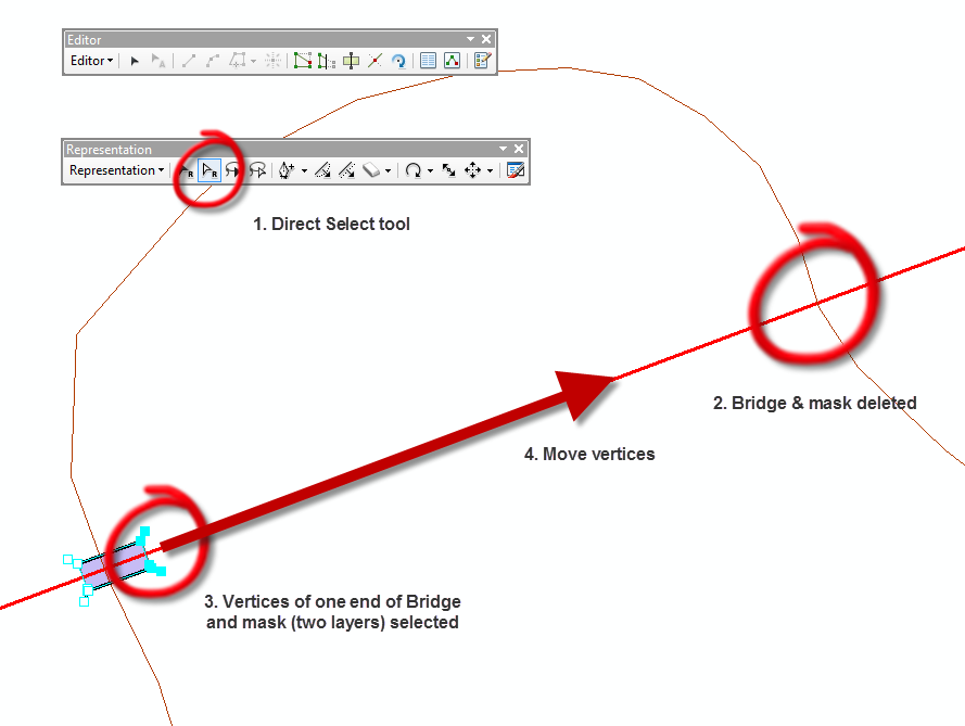
Figure 8. Manual editing vertices of the mask and parapet feature classes
Release the mouse and you should have created a longer parapet and mask combination (figure 9).
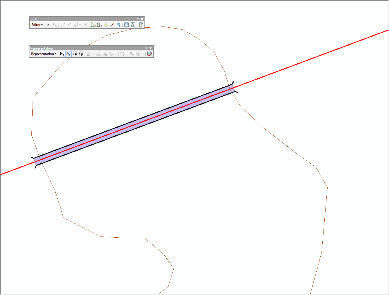
Figure 9. Edited mask and parapet feature class
Once you have done your manual edits, save the edits and exit your Edit session.
The final step to achieve the desired effect requires you to use Symbol Level Drawing. Right-click the data frame name in the Table of Contents and select “Advanced Drawing Options”. Here, opt to “Draw using masking options specified below”. Then select as the Masking Layer your edited mask layer (over_FC_rep_singlepart, in our example) and set the masked layer to be the original polygon feature class (lake_Rep, in our example) plus any other layers you wish the mask to cover. then click OK (figure 10).
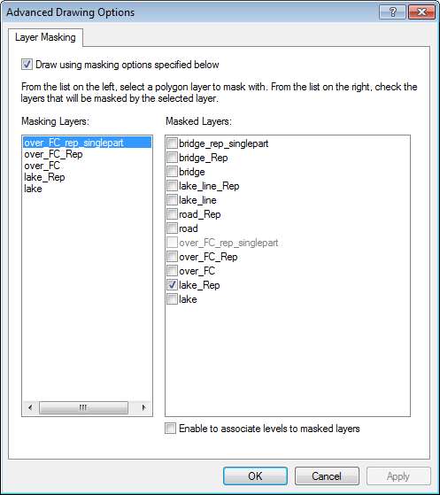
Figure 10. Applying masking options for Symbol Level Drawing
Now when you unselect the polygon boundary line feature class and the mask layers in the Table of Contents you should see that you have created overpass symbology that cuts across a polygon (figure 11).
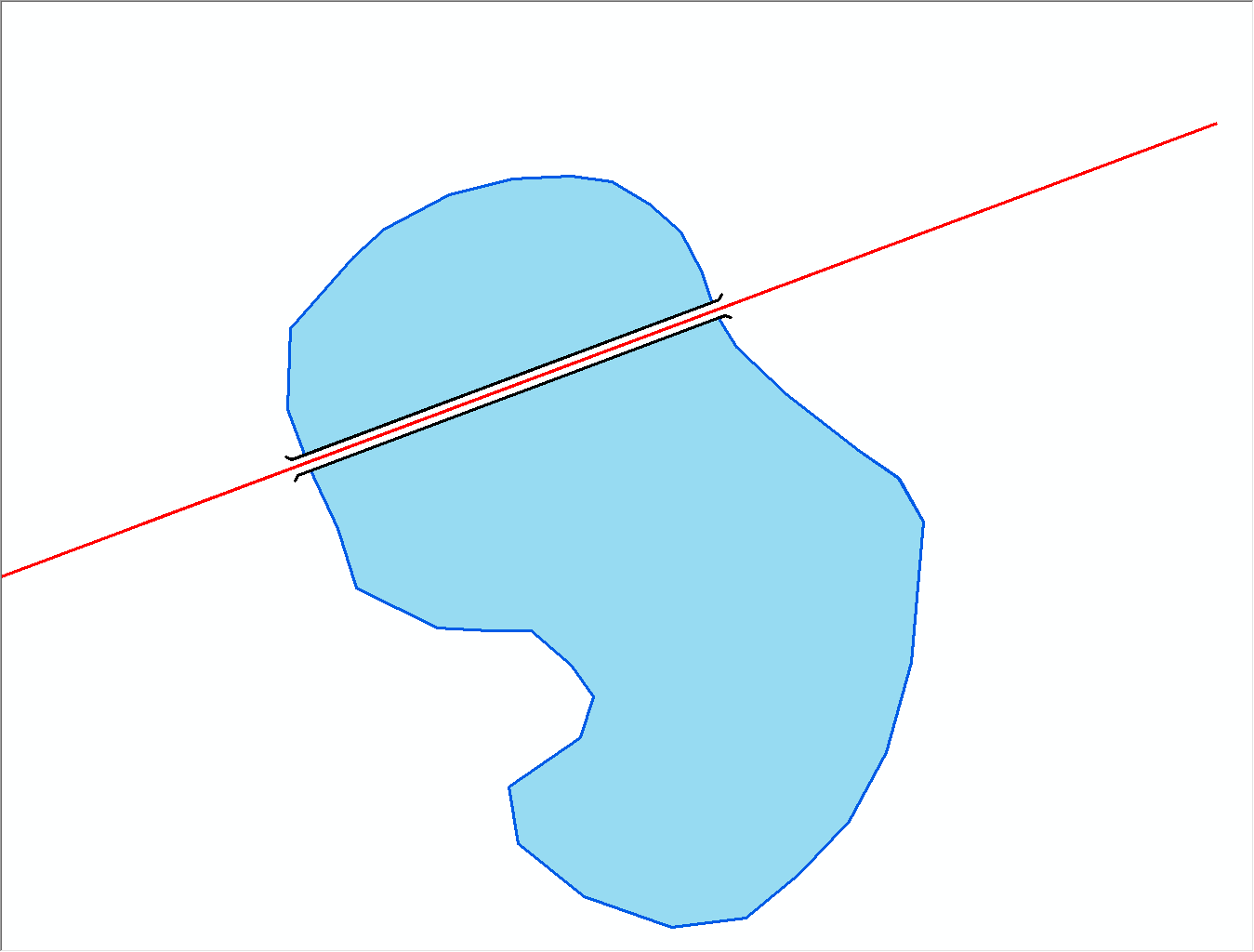
Figure 11. Final result showing the masked bridge parapet extending across the lake polygon
This process works well when you have straight lines across a polygon. If you have curved lines and require a more complex mask and parapet symbology the process is the same except you will need to do more manual editing to add new vertices to the mask and parapet features to shape it so that it follows the geometry of your original line feature class. Figure 12 shows how your features might look in this situation.
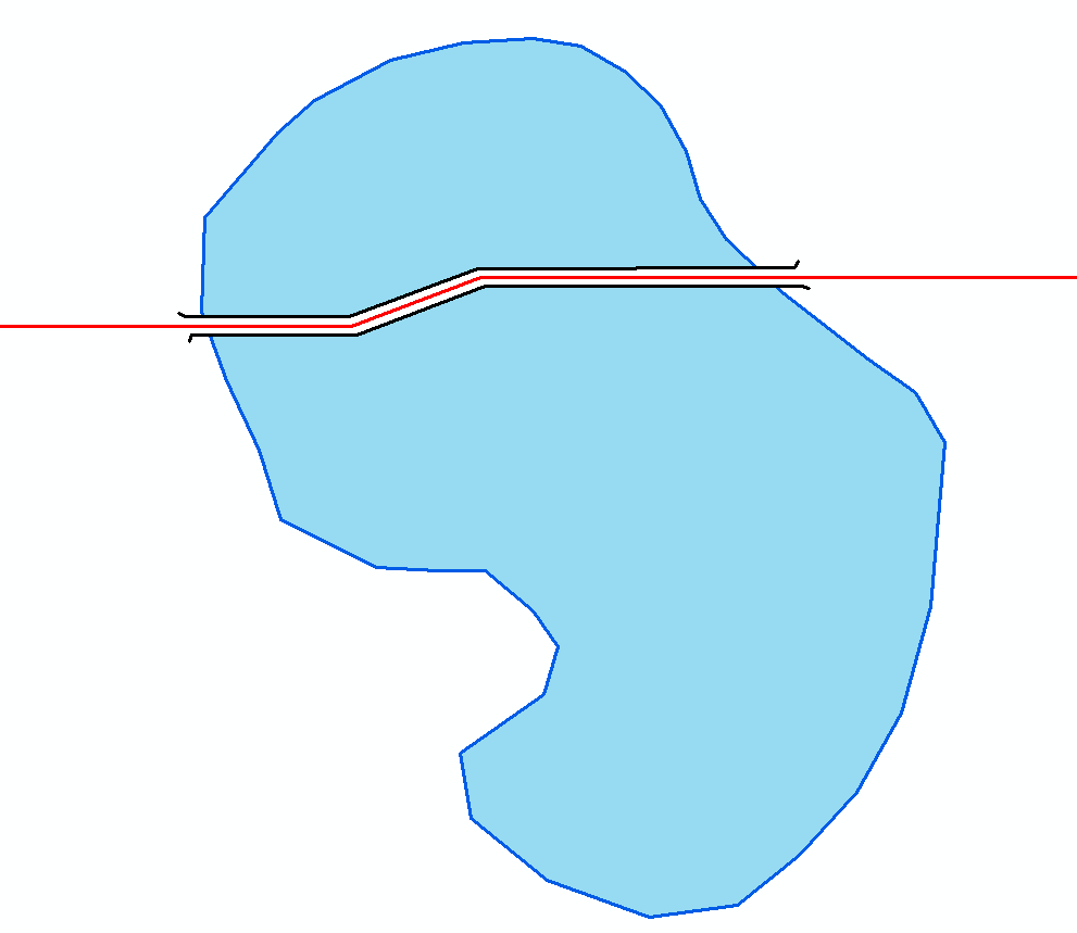
Figure 12. Result showing modified mask and parapet features for the case of a line that is not straight
This workflow will help you create overpasses for line-over-polygon situations. If you think this is a technique that would be more useful as part of the standard Create Overpass tool then please request the tool to be enhanced by posting your request on the ArcGIS Ideas Web site.
Thanks to Marc-Olivier Briat, Software Product Developer, and Aileen Buckley, Mapping Center Lead, for their help with this blog entry.

Article Discussion: