This post was originally published on January 8, 2014, and has been updated. The last previous update was January 6, 2025.
Symbols can be rotated to display compass direction, such as the direction a vehicle is traveling, a camera is pointing, or the wind is blowing. In addition to rotating symbols to show compass direction, you can also use symbol rotation to display values.
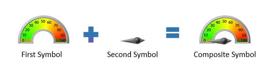
This blog article will detail a technique that can be used to display values in gauges on your map using layered symbols for the dial and needle and rotating one of them.
An example
The map below uses stacked symbols to show locations. The needle symbol is rotated using a value associated with the location. The value shown on the dial ranges from zero to 100. Note that each dial is displaying a unique value.

To create the dial symbols, the layer was duplicated and uses two overlapping symbols; one symbol is the dial and the other symbol is the needle on the dial. The needle is rotated using an attribute field to rotate the needle to display a value on the gauge.
In the sample map, these have been placed into a gauge group layer.

Depending on your implementation, there may be some changes that need to be made to your gauges or to the data that enables the rotation of gauge elements. With the default geographic rotation of symbols, rotation values rotate the symbol clockwise.
The rotation values for the dial were calculated based on the default orientation of the needle (directly to the left) and the value to be displayed. For example, to move the needle to point to a value of 50 on the gauge, the needle should be rotated 90 degrees clockwise. To move the needle to point to a value of 75 on the gauge, the needle should be rotated 135 degrees clockwise, and so on.
Try it yourself
To make your own gauge and dial map, sign in to your organization, and follow these steps.
Step 1 — Open the sample map. You can sign in to your account to save the map, or following along without signing in.
Step 2 — In the Contents (dark) toolbar, open the layers pane. The map has two group layers; one group layer is fully configured, the other is unconfigured. Hide the Gauge group layer and show the Gauge (unconfigured) group layer.

Step 3 — View and save the dial and needle symbols shown below. These will be used to create the gauge.


Step 4 — Open the Gauges (unconfigured) group layer and select the Needle layer.

Step 5 — View the layer pop-up. CW_Rotation is the field containing the rotation value that will be used for the symbol.

Step 6 — In the Settings (light) toolbar, open the Properties pane and click Edit layer style.

You can also open the Styles pane from the Settings toolbar to advance to Step 5.
Step 7 — The layer is symbolized using a single symbol. Click Style options in the second section.

Step 8 — Click to edit the current symbol style.

Step 9 — The current symbol is of type Basic point. Click to change it.

Step 10 — Click Symbols in the Uploaded Symbols category.

Step 11 — Click Browse to navigate to the needle image you saved on your local drives in Step 3 above, and select it to use it as your point style. Click Done after you select it.

Note: Uploaded symbols will persist until you clear browser cache, so you can go back and reuse them. Once added, uploaded symbols can be sized, rotated, and have effects applied like any other symbol.
Step 12 — Adjust the symbol size to 100 px.

Step 13 — Make the following changes in the Rotation by attribute section.
a – Toggle Rotate symbols based on attribute values on.
b – From the field drop-down, choose CW_Rotation. As noted in Step 5, this is the field containing the rotation to be applied.
c – Ensure that Geographic rotation is toggled on. The CW_Rotation rotation values are expressed in compass direction.

Step 14 — Repeat steps 4 through 10 for the Dial layer using the dial image downloaded and saved in Step 3. Note that the dial is static and does not need to be rotated.
When finished, your map should look similar to what is shown below.

Step 15 — Finalize your map by configuring layer pop-ups, omitting the layers from the legend, and renaming the group layer. When finished, Save the map.
More information
With a little bit of creative thinking, you can do some very interesting and clever things with layering and rotating symbols. For more information see:
- Rotate point symbols in web maps (ArcGIS Blog)
- Use images as custom point symbols (ArcGIS Blog)
- Change style (Help)
Commenting is not enabled for this article.