In Part I of this blog series, we explained what an ortho mapping workspace is and how to create one for digital aerial imagery. At this point, the imagery has been organized and managed so that we can access all the necessary metadata, information, tools and functionality to work with our imagery, but we haven’t yet performed a bundle block adjustment.

Block adjustment is the process of adjusting the parameters in the image support data to get an accurate transformation between the image and the ground. The process is based on the relationship between overlapping images, control points, the camera model, and topography – then computing a transformation for the group of images (a block). With aerial digital data, it consists of three key components:
- Tie points – Common points that appear in overlapping images, tying the overlapping images to each other to minimize misalignment between the images. These are automatically identified by the software.
- Ground control points – These are usually obtained with ground survey, and they provide references from features visible in the images to known ground coordinates.
- Aerial triangulation – Computes an accurate camera model, ground position (X, Y, Z), and orientation (omega, phi, kappa) for each image, which are necessary to transform the images to match the control points and the elevation model.
When we created our workspace, we provided the Frames and Cameras tables, which contain the orientation and camera information needed to make up our camera model and to establish the relationship between the imagery and the ground. We also provided an elevation model which we obtained from the Terrain image service available through the Living Atlas of the World. Now we’re ready to move on to the next step in the ortho mapping process.
Performing a Block Adjustment for Digital Aerial Data

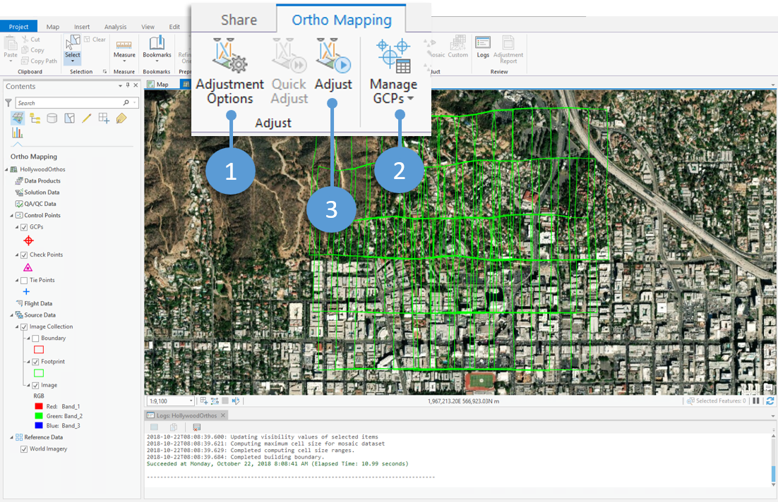
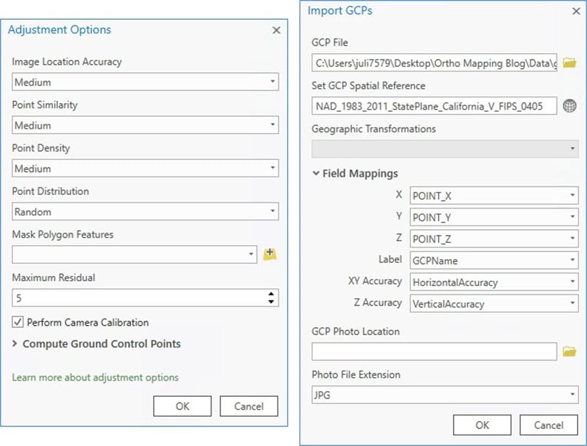
- In the ortho mapping workspace, open the Ortho Mapping tab and select Adjustment Options from the Adjust group. This is where we can define the parameters used in computing the block adjustment, which includes computing tie points. For more information on each parameter, check out the Adjustment Options help documentation.

- Next, we want to add Ground Control Points (GCPs) to our workspace to improve the overall georeferencing and accuracy of the adjustment. To do this, select the Manage GCPs tool in the Ortho Mapping tab and choose Import GCPs. We have a CSV table with X, Y and Z coordinates and accuracy to be used for this analysis.
- If you have an existing table of GCPs, use this Import option and map the fields in the Import GCPs dialog for the X, Y, and Z coordinates, GCP label, and accuracy fields in your table. You may have photos of each GCP location for reference – if so, you can import the folder of photos for reference when you are measuring (or linking) the GCPs to the overlapping images.
- You may also have secondary GCPs, or control points that were not obtained in a survey but from an existing orthoimage with known accuracy. You can import those here as well, or you can manually add them using the GCP Manager.
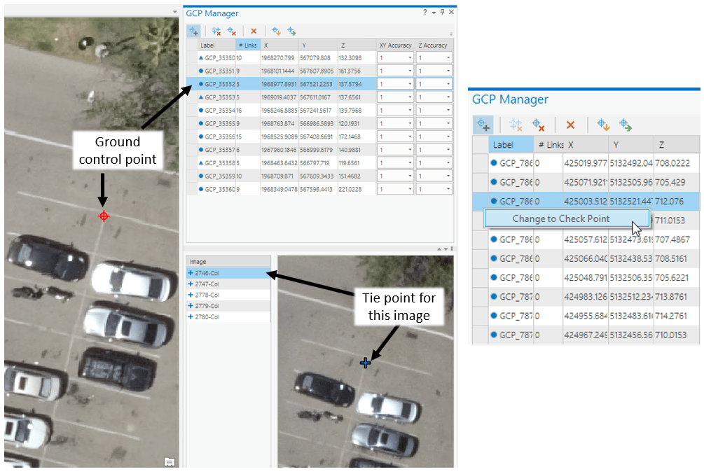
- Once you have added GCPs to the workspace, use the GCP Manager to add tie points to the associated locations on each overlapping image. Select one of the GCPs in the GCP Manager table, then iterate through the overlapping images in the Image list below and use your cursor to place a tie point on the site that is represented by the GCP

A few notes
- Check Points: Be sure to change some of your GCPs to Check Points (right-click on the GCP in the GCP Manager and select “Change to Check Point) so you can view the check point deviation in the Adjustment Report after running the adjustment. This is essentially changing the point from a control point that facilitates the adjustment process to a control point that assesses the adjustment results.The icon in the GCP table will change from a circle to a triangle, and the check points appear as pink triangles in the workspace map.
- Drone imagery: If you are performing a block adjustment with drone imagery, you must run the Adjust tool before adding GCPs. In this blog, we’re focusing on aerial digital data.
- Finally, we click the Adjust tool to compute the block adjustment.
This will take some time – transforming a number of images so that they align with each other and the ground is complicated work – so get up, maybe do some stretches or get yourself a cup of coffee. The log window will let you know when the process is complete. When the adjustment is finished, you’ll see new options available in the ortho mapping tab that enable you to assess the results of the adjustment.
Assessing the Block Adjustment

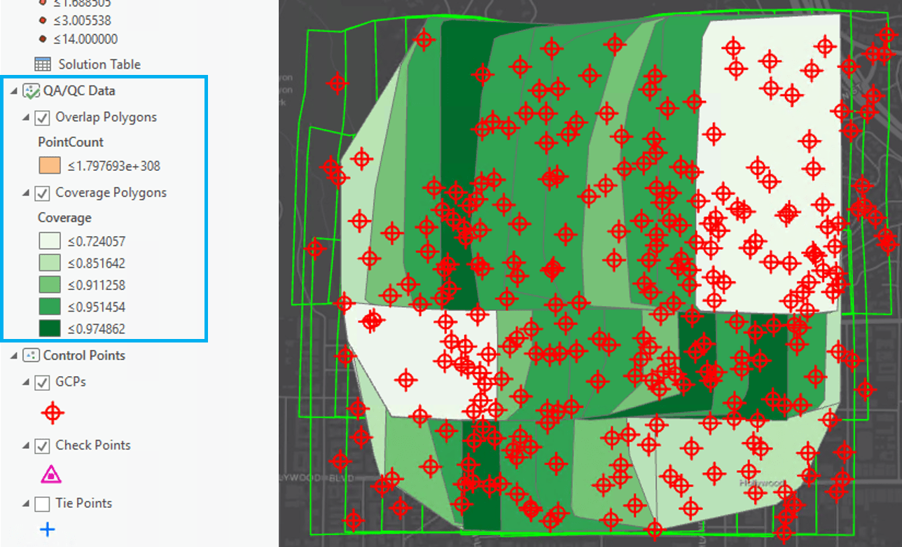
- Run the Analyze Tie Points tool to generate QA/QC data in your ortho mapping workspace. The Overlap Polygons feature class contains control point coverage in areas where images overlap, and the Coverage Polygons feature class contains control point coverage for each image in the image collection. Inspect these feature classes to identify areas that need additional control points to improve block adjustment results.

- Open the Adjustment Report to view the components and results of the adjustment report. Here you will find information about the number of control points used in the adjustment, the average residual error, tie point sets, and connectivity of overlapping imagery. In our case, the Mean Reprojection Error of our adjustment is 0.38 pixels.
Now what?
The block adjustment tools allow for an iterative computation, so that you can check on the quality of the adjustment, modify options, add or delete GCPs, or recompute tie points before re-running the adjustment. If you are unsatisfied with the error in the Adjustment Report, try adding GCPs in the Manage GCPs pane, or try modifying some of the Adjustment Options. You can also change some of your check points back into GCPs, and choose a few other GCPs to be your check points. Re-run the adjustment and see how this impacts the shift.
Once you are satisfied with the accuracy of your adjusted imagery, it’s time to make ortho products! Check out the final installment in our blog series to see how it’s done.

Commenting is not enabled for this article.