Creating accurate high-quality 2D and 3D products in Drone2Map, starts with good data collection practices in the field. Here are some quick tips to help you a plan a successful drone mapping mission.
Use the Ground Sampling Distance that Fits your Requirements
One of the most important factors to consider when planning a drone flight is the Ground Sampling Distance (GSD) of your project. GSD is the amount of ground that will be sampled by each image pixel.
The GSD is determined by your camera and the altitude of your flight. As you lower the altitude of your drone the GSD of your images decreases, allowing you to see more detail in your images and increasing the accuracy of your drone mapping products.

Is more always better?
It may seem logical to use the smallest GSD value for every project. After all, more detail and accuracy are better, right? However, decreasing the GSD will require more images to cover the same area, which means longer flight times, processing times, and increased disk space requirements. Instead, use the highest GSD that fits your project requirements to create cost-effective products.
Define your Accuracy Requirements
There are two ways to measure the accuracy of your drone mapping products: absolute and relative.
Relative accuracy is a measure of how well the dimensions of features within your drone mapping products model their real-world dimensions, independent of their actual location in the world. Maps with a high relative accuracy are useful for marketing, measuring distances, angles, and volumes, or creating vegetative indexes.

Absolute accuracy is a measure of how well feature in your mapping products align with their real-world location. A high absolute accuracy is important when you need to know the exact location of features in your map or when comparing your mapping products to other geographic information.
With proper image collection techniques modern drones are capable of producing mapping products with a high relative accuracy. However, the on-board GNSS receiver is usually not adequate for creating mapping products with a high absolute accuracy. If this is a requirement, you may need to include Ground Control Points in your project.

Use Ground Control Points for High Accuracy
Ground Control Points (GCPs) are easily identifiable markers with a known geographic location that are used to align your mapping products to a know coordinate system to a high degree of accuracy.
GCPs can be collected in the field with a GPS, derived from LiDAR, or calculated from Elevation Services within Drone2Map. Whichever source you use, it’s important to note that the absolute accuracy of your mapping products cannot be higher than the accuracy of the GCPs. Therefore, it’s recommended that GCPs are collected with greater accuracy than the expected accuracy of your mapping products.

When using GCPs, try to distribute them evenly throughout your entire project area, in a triangle-grid pattern to minimize the distance between each GCP. The grid doesn’t have to be perfect but avoid having GCPs clustered in one area of your project to ensure uniform accuracy throughout your project.
The optimal amount of GCPs will depend on your project. Generally, the more GCPs you have, the more accurate your results. However, the increase in accuracy after 10 GCPs is usually insignificant unless you’re mapping complex terrain. A Drone2Map project only requires three GCPs, but it’s recommend to use at least five GCPs – one in each corner of your project and one in the center.

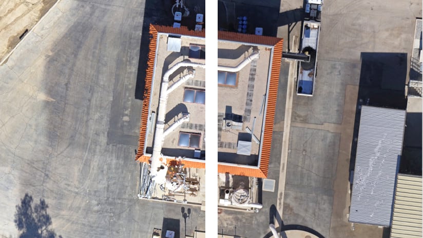
GCPs should be placed on a flat surface away from changes in elevation, such as the edge of cliffs, street curbs, or on top of small objects. In addition, the location should be visible in as many images as possible. Watch out for any nearby objects that could obstruct the view between the drone and the GCP, such as trees, powerlines, and buildings. If the GCP is obstructed in an image, air on the side caution and do not mark the GCP in that image.
There is no standard for what can be used as a GCP. However, the type of GCP you use should match the accuracy requirements of your project. For example, natural and manufactured features – such as rocks, maintenance holes, and the corners of pavement – can be convenient options for GCPs. However, these types of GCPs are usually less accurate and poorly distributed throughout your project area. For the most accurate results, it’s best to use checkboard targets.

Verify Your Accuracy with Checkpoints
A common metric for determining the accuracy of your mapping products is that the horizontal accuracy will be 1 to 3 times the GSD and the vertical accuracy will be 1 to 5 times the GSD. While this may be a good guideline for estimating accuracy, the only way to truly quantify the accuracy of your drone mapping products is to use checkpoints.
Checkpoints are collected identical to Ground Control Points, but are not used during processing. Instead, they are used after processing to independently validate the accuracy of mapping products by measuring the distance between the location of the checkpoint in your processed products with its real-world location.

Use the Right Flight Plan
Flight planning is an important part of a successful drone mapping mission. While it’s possible to create mapping products by manually flying a drone, using a flight planning software, such as Site Scan LE, will ensure that your images are collected at a consistent altitude and with proper overlap for efficient and reliable results.
For more information on the type of flight plans and when to use them, see the tech support FAQ: What are the flight modes available in Site Scan Flight for ArcGIS?
Increase Overlap
Generally, the more overlap you have the more accurate your results will be. Increasing overlap will also help with the reconstruction of complex geometries and homogenous image textures, such as agricultural fields, dense vegetation, and urban environments. When planning a mission, start with 80 percent overlap and 80 percent sidelap to ensure good coverage of your project area and maximize the accuracy of your products. Reduce the overlap as needed, starting with the sidelap first, but avoid going below 70 percent overlap and 65 percent sidelap.
It’s important to be aware of any elevation changes in your project area when setting your overlap. Flight software will generally calculate overlap using the height at the point of take-off. If your drone then flies over an area with higher elevation, such as hills and buildings, the overlap of your images will be reduced and may lead to issues during processing. When possible, take-off from the highest point in your project area or increase your overlap to compensate for any elevation changes.
Symptoms of poor overlap include:
- Incorrect or missing data in your processed products, such as poorly reconstructed buildings.
- Reduced absolute and relative accuracy.
- Dropped images or errors during processing.

Increase the Size of Your Project Area
The edges of your project have less overlap due to the lack of adjacent flight tracks. As a result, the edges will generally be less accurate. In addition, the sudden change in direction as your drone transitions to the next flight track can momentarily degrade the accuracy of the onboard GNSS receiver. To ensure your entire project area is processed with maximum overlap and with a good GNSS fix, create a flight plan that covers an area slightly larger than your area of interest.

Capture High-Quality Images
Image quality is an important factor to the success of your drone mission. Low quality images degrade the performance of photogrammetry software which can lead to issues, such as dropped images, reduced accuracy, and inconsistent color balancing to name a few. Luckily, you don’t need to be an artist to take high-quality images for drone mapping, simply learning the fundaments of taking sharp images can significantly improve the quality and consistency of your drone products. Below are a few factors than can influence the quality of your images.
Lighting
Weather – Consistent lighting is important for capturing high-quality drone images. Sunny days may seem like the ideal lighting conditions, but highly contrasting shadows and the glare from reflective surfaces can be problematic for photogrammetry software. A bright overcast day can produce the best quality images since the clouds diffuse the sunlight, creating soft consistent lighting with little to no shadows.

Time of Day – Plan your flights around solar noon when the sun is highest in the sky to reduce the intensity of shadows and glare. If you project requires multiple flights, avoid taking long breaks between each flight where the lighting conditions may have changed, such as morning and evening.

Speed
Fly your drone as slow as possible to reduce motion blur. Motion blur occurs when the camera moves faster than the time it takes to capture the image. This causes the information being collected by an image pixel to appear in adjacent pixels, resulting in blurry images. While it’s not possible to completely eliminate motion blur, increasing the GSD or reducing the flight speed so that the motion blur is less than the GSD can help mitigate the effects.

Challenging Scenes
Sometimes it’s not the quality of the image but what’s being photographed that can be the issue. For example, all drone mapping software has difficulty processing images that contain repeating patterns, such as forests, grasslands, agricultural fields, and building facades. If you’re having difficulty processing these areas, increasing the overlap of your images or the altitude of your drone can produce better results in these conditions. In addition, avoid taking images that capture the horizon, contain lots of moving objects, or flights over large bodies of water.
Remove Problematic Images
After you’re done with your drone flight, it’s a good practice to review your drone images and remove any that may cause errors during processing, such as:
- Blurry images.
- Over- and underexposed images.
- Images that contain large portions of the horizon.
- Images with an obstructed view of your project area.
Use the Right Coordinate System
Knowing the coordinate system that your drone uses to geotag images is important for creating accurate mapping products. This can be confusing when using an RTK GNSS drone as different manufactures process base station correction differently. For drones that are designed for mapping, this usually means a quick look at the user’s manual. However, lower-end consumer drones may require a bit of research.


Article Discussion: