ArcGIS Pro 3.5 introduces a Rail Selection tool that facilitates the interactive classification of points captured along rail tracks in mobile lidar point clouds. This blog article briefly describes how the rail selection process works and shares tips for using it effectively.
Before you begin
Mobile lidar point clouds can be extremely dense or stored in large files, which may negatively impact display and analysis performance. To improve efficiency, it’s recommended to apply tiling and thinning techniques to ensure an appropriate tile size and point density. Additionally, building pyramids can significantly improve display performance. Dense rail data without pyramids may render much more slowly.
Use the Rail Selection tool
To use the Rail Selection tool, complete the following steps:
- In the local scene, select a LAS dataset layer in the Contents.
- On the Classification tab in the ribbon, in the Selection group, click Select > Rail.
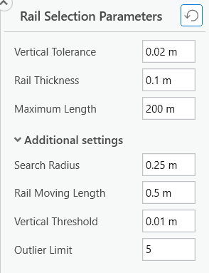
This opens the Rail Selection tool window, where you’ll find primary and additional parameters with default values. While these defaults are generally sufficient, you may need to adjust them to accommodate data noise, track types, or more complex conditions, such as low-quality data, sharp curves, and at-grade crossings.

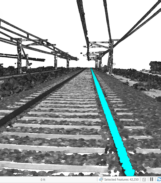
- To start the selection, either double-click a rail point, draw a short line along the track, or sketch a small polygon around a rail segment.
Upon completion of the selection, the count of selected rail points is displayed at the bottom of the view. A spinning wheel on the right indicates the progress of rendering the selection. Drawing may take a long time if a large number of points are selected.

Once the wheel stops spinning, the selected points are rendered, and the spinning wheel reverts to a refresh button.

After you’ve verified that the selected points correctly represent rails, you can assign them a class code (typically 10 for rail).
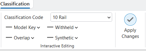
- Go to the Interactive Editing group on the Classification.
- From the Classification Code drop-down list, select 10 Rail.
- Click the Apply Changes.

Understand the rail points selection process
The rail selection process begins by identifying seeds. The tool evaluates the selected points and determines whether they qualify as seeds.
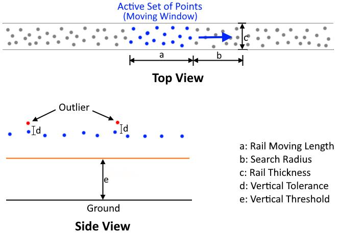
Once the seeds are established, the tool constructs an active set of points that functions as a moving window, which searches for nearby points and adds those that are evaluated as rail. When the moving window exceeds the specified rail moving length, it splits into two windows that then move in opposite directions along the rail. As each window advances, it searches for candidate rail points within a specified search radius from the front of the window.
Points are iteratively added to the active set if they meet all of the following criteria:
- Points fall within the specified rail thickness.
- Points have neighboring points below them by at least the vertical threshold.
- Points are within the vertical tolerance of the established rail level in the current set.
The selection process stops when no additional points within the search radius qualify as rail, or when the maximum length is reached. All points added to active sets make up the final rail selection. Fig. 5 illustrates the parameters used in the rail selection process.

Recommendations and tips
To use the Rail Selection tool effectively, it is important to understand how each parameter affects its behavior. The following recommendations and tips provide best practices for setting up and using the tool, helping you avoid common pitfalls and achieve accurate, reliable results.
- Ground points are essential for the algorithm to evaluate and identify rail points and must remain in the layer without being filtered out. While classification is not required, it is recommended that you classify the ground points.
Other above-ground points can be filtered out to improve display performance. For example, you can use the Elevation Range filter to remove high points such as power lines and bridge decks or apply the Classification filter to exclude vegetation points if they have already been classified.
- The tool processes full-resolution data regardless of displayed level of details (LOD), so it’s not necessary to display the data in full resolution during selection.
- Adjust Vertical Tolerance based on the noise level in the data. Use a larger value for noisier data.
- Set Rail Thickness according to the actual rail type. If edge points are not selected, try increasing the value. If points beyond rail edges are included in the selection, try decreasing the value.
- Maximum Length defines the maximum allowable distance in each direction from the initial seed points. While you can select very long rail segments, keep in mind that processing time increases linearly with length. Adjust the maximum length as needed to keep reasonable processing times.
- The Search Radius value should be large enough to bridge gaps along the rail. However, setting this value too high can significantly slow down the selection process.
- A larger Rail Moving Length value is recommended for selecting points on straight rails. When having problems selecting points on curves, try decreasing the value.
- Vertical Threshold defines the minimum above-ground distance for a point to qualify as a rail point. Use a smaller value for lower tracks and a larger value for higher tracks.
Selecting rail points at-grade crossings is challenging, as the ground and rail are at the same height with only a shallow groove along the inner rail for the wheel flange. In this case, a smaller vertical threshold and a longer rail moving length should be used.
- The tool continually checks for outliers. If the count of outliers within the window is below the specified Outlier Limit value, they are ignored. If it exceeds the limit, the outliers are treated as rail points, which lead to elevated rail profile or even halt the selection process.
After selecting the rail points, use the Interactive Editing tool to assign a class code. The classified rail points can serve as training data for deep learning models. Once rail points are classified, you can extract rails and centerlines from them. For more details, refer to the Extract rails and centerlines from mobile lidar point clouds blog article.
Article Discussion: