ArcGIS Pro network diagrams integrated with the utility network and trace network reuse most of the ArcGIS Schematics extension basics and concepts. However, some differences prevent an easy and automated migration of your schematic diagrams to network diagrams.
This blog explains the four stages required to port ArcGIS Desktop schematic diagrams to ArcGIS Pro network diagrams. The first stage consists of migrating the dataset to an ArcGIS Pro utility network or trace network. The second stage entails identifying the schematic diagrams that can be ported and analyzing how they were built. Based on this analysis, the third stage is configuring new diagram templates for the newly migrated ArcGIS Pro network and re-creating the expected network diagrams. When the new ArcGIS Pro network diagrams look like to those created with the ArcGIS Schematics extension, except regarding their layout, the last stage can consist of exporting the schematic diagram layouts before importing them to the new network diagrams.
The sections below give you some guidance for each stage.
Migrate to a Utility Network or Trace Network
The first stage uses ArcGIS Pro and consists of migrating your dataset to an ArcGIS Pro utility network or converting your geometric network to an ArcGIS Pro trace network.
Even if this stage focuses on your network data, you must verify a point that is required for schematic layout migration later. Before migrating any data, ensure that any network feature or object used to create your schematic diagrams exists in your dataset with a Global ID. These Global IDs are prerequisites for porting your schematic diagram layouts to your new network diagrams.
If Global IDs are missing from some or all network features or objects, use ArcGIS Catalog and start with the following changes:
- Run the Add Global IDs geoprocessing tool to add missing global IDs to the geodatabase feature classes or tables.
- Run the Update Diagrams geoprocessing tool to update your schematic diagrams accordingly. Once the update completes, each schematic feature in the schematic feature classes will get a non-empty UGUID field value corresponding to its associated network feature/object Global ID.
Then, go back to ArcGIS Pro and migrate your dataset to a Pro utility network or trace network. During this process, you must make sure you load the features and objects into the appropriated network source classes and object tables while preserving these Global IDs.
The next steps consist of defining the network rules, and network attributes, and any other process that will make your network operational. The goal is to have a clean enabled network topology from which you will build your first network diagrams.
Analyze Schematic Diagram vs Network Diagram Builds and Settings
It is time to focus on the schematic diagrams porting feasibility. This means identifying the schematic diagrams that may be ported and analyzing how they were built. This is done using ArcGIS Desktop.
You can start Schematic Dataset Editor, load your schematic dataset, and review your schematic diagram template settings.
For each schematic diagram template, you must first verify the schematic builder.
- Schematic diagrams created using the Standard builder configured to directly process network features are good candidates for porting.
- For schematic diagrams based on the XML builder or on the Standard builder configured to process custom queries, porting them depends on how the XML data or queried features/objects were migrated to your ArcGIS Pro network. If there is a corresponding feature, object, or association in your new utility or trace network, you have a good chance porting these successfully.
- Schematic diagrams based on the Network Dataset builder cannot be ported.
Continue by analyzing the content of your ArcGIS Schematics diagrams and the schematic rules specified on their related schematic diagram template.
The sections below describe the differences between schematic diagrams and network diagrams and discuss the way the diagram-building processes operate. It is critical to understand all these concepts and differences to know whether each schematic diagram template you worked with in ArcGIS Desktop can be re-created for your new ArcGIS Pro utility network or trace network.
Polygon or polyline containers
Polygon and polyline containers in schematic diagrams
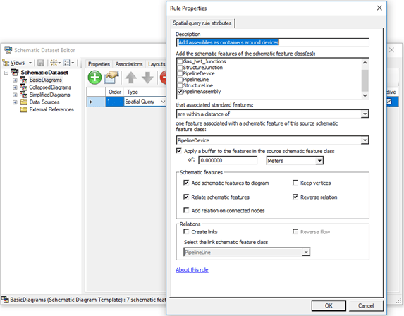
Schematic diagram features representing polygon or polyline containers can relate features or objects even if one of them is out of the geometric network. We use either a Spatial Query rule or a Relationship rule to create containers in schematic diagrams.
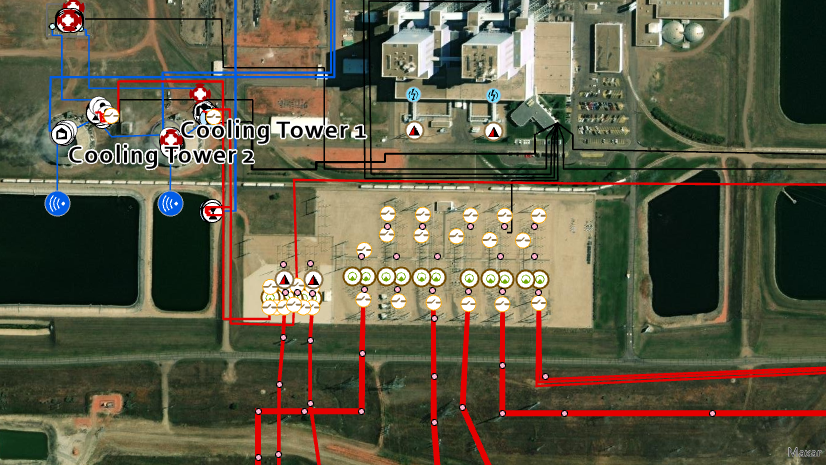
In the use case below, a Spatial Query rule is set up to systematically add assemblies that are close to a device and draw them as polygon containers around their related devices:
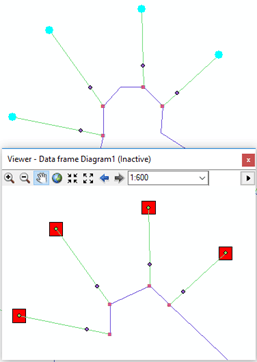
The resultant diagram below shows the added assemblies as red polygon containers around their related device:
Polygon and polyline containers in network diagrams
The utility network supports containment associations between network features or network objects. These container-content relations become part of the utility network index at network topology validation. On the network diagram side, any utility network content feature is created in a network diagram with its related polygon diagram container by default. This happens without specifying any diagram rule on the diagram template. There is no other way to create diagram containers in a network diagram. Diagram containers only represent utility network containment associations.
Learn more about containment associations in network diagrams
Spatial Query rules
Adding features to schematic diagrams using a Spatial Query rule
With ArcGIS Schematic extension, the Spatial Query rule detects new features based on where they are located in relation to the features in input, and appends these detected features to the generated schematic diagram. Nothing prevents you to query a network feature related to a feature that is outside the geometric network and get both of them represented in your schematic diagrams.
Moreover, you have the ability to represent the relationship between the input and added features. For example, when the input and added features are two schematic nodes in the diagram, you can configure the Spatial Query rule to automatically add a schematic link between these two nodes. Another use case is when the input or added feature has a polygon or polyline geometry on the diagram side. In this case, it comes in the schematic diagram as a rectangle container polygon that displays around its related contents.
Adding features to network diagrams using a Spatial Query rule
In ArcGIS Pro, the Spatial Query rules that you can set up on your diagram templates are quite limited. They only operate on feature classes that are part of the utility network or trace network; that is, feature classes that are outside the network are not supported.
Moreover, you have no way to add any diagram edge or diagram container to represent a relationship between the input and added features.
Collapse rules
Collapsing features in schematic diagrams
The Collapse Related Features rule provided with the ArcGIS Schematics extension collapses schematic features with containment associations. These containment associations exist on the schematic diagram level and mainly result from a Relationship rule or a Spatial Query rule applied prior during the schematic diagram build process.
Collapsing features in network diagrams
With ArcGIS Pro, there is no Relationship rule and the Spatial Query rule doesn’t allow related features. The Collapse Container rule is the only way to get features to collapse in network diagrams. A collapse operation performs containment associations included with the utility network. Without containment associations on the network side, you cannot collapse containers during any network diagram build process.
Remove features rules
Removing features in schematic diagrams
To automatically remove features in your schematic diagrams, you configured the Feature Removal rules on your schematic diagram template.
Removing features in network diagrams
The Remove Feature rule is used to build network diagrams and processes features similarly.
NOTE: You may have to configure Remove Feature rules on your network diagram templates more often than you were used to doing on your schematic diagram templates. For example, if you want to have content features represented in your diagrams without their related containers when generating diagrams from utility networks, you will have to configure the Remove Feature rules to have them systematically removed.
Reduce junctions rule
Reducing junctions in schematic diagrams
There are three schematic rules to configure junction reductions for your schematic diagram templates—Node Reduction by Priority, Node Reduction by Flow and Route Node Reduction rules.
Reducing junctions in network diagrams
Whether your network is a utility network or trace network, there is only one diagram rule to set up on your diagram templates to reduce junctions; it is called Reduce Junction rule.
The ArcGIS Pro Reduce Junction rule merges most of the Desktop schematic node reduction rules functionality. For example:
- They can be configured to work with attribute constraints.
- They keep track of any reduced junction and its connected edges either on the diagram junction that is considered the target junction by the reduction rule or on the reduction edge, which is created by the rule
- They run individually as an iterative in-memory process
- They can be configured to run according to attributes on the incident edges.
However, there are some differences in the reduction process. These differences are listed in the sections below:
1. The schematic node reduction process considers the adjacent links, while the diagram junction reduction process considers the adjacent junctions
| ArcGIS Desktop schematic diagrams | ArcGIS Pro network diagrams |
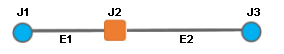
| Any schematic node reduction depends on the number of its adjacent links, that is, the number of links connected to the schematic node to reduce.
In the graphic below, the orange schematic node J2 has two adjacent links, E1 and E2: |
Any diagram junction reduction depends on the number of other diagram junctions to which it is connected, that is, the number of its adjacent diagram junctions.
In the graphic below, the orange diagram junction J2 has two adjacent diagram junctions, J1 and J3: |

2. There are topological differences when reducing schematic nodes with two adjacent links vs reducing diagram junctions with two adjacent junctions
| ArcGIS Desktop schematic diagrams | ArcGIS Pro network diagrams |
| Depending on the node reduction rule settings, a node with a minimum of two adjacent links is reduced to one of the following: A. The nearest adjacent node (default) For example, when reducing the blue node J2 below, the shortest link E2 is reduced with the blue node to the nearest node J3, and the longest link E1 is reconnected to that nearest node. This is the default result. 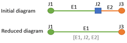 B. The adjacent node with the highest priority For example, when reducing the blue schematic node J2 below that is connected to the green node J1, and this one is configured with the highest priority, the green link E1 and the J2 node are reduced to J1 and the other link E2 is reconnected to the green node J1, which priority is the highest: 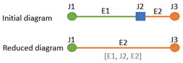 |
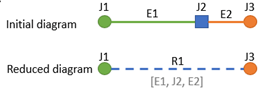
The reduction of diagram junctions with two adjacent junctions is not tied to any specific setting. Such a diagram junction is reduced in the same way whatever its adjacent junctions.
It results in the creation of a new diagram edge, called a reduction edge, that connects the two adjacent junctions.
|
3. There are topological differences when reducing schematic nodes with three adjacent links or more vs reducing diagram junctions with three adjacent junctions or more
| ArcGIS Desktop schematic diagrams | ArcGIS Pro network diagrams |
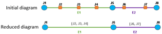
| The same as when reducing nodes with two adjacent links, it depends on the reduce junction rule settings. A node with three adjacent links or more is reduced to one of the following: A. The nearest adjacent node (default) For example, when reducing the blue node J5 below, the shortest link E5 is reduced with the blue junction to the nearest node J6, and the other connected links E3 and E4 are reconnected to the nearest node J6: 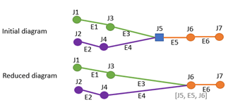 B. The adjacent node with the highest priority When reducing a blue node J5 connected to a green node J3 configured with the highest priority, the green link E3 connecting these two nodes is reduced with J5 to the highest priority node J3 and all the other links E5 and E4 are reconnected to that node. 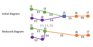 |
The reduction of diagram junctions with three adjacent junctions or more is not tied to any specific setting. Such a diagram junction is systematically reduced to the upstream junction when this junction is unique. When more than one upstream junctions is detected, there is no reduction. For example, to reduce the blue node J5 below, the process retrieves all the junctions that are upstream of it. 1. In the sample below, since it detects a unique upstream junction J6, the reduced junction J5 and the edge between J5 and J6 are systematically reduced to J6. 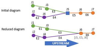 2. In this second sample below, since both J3 and J4 are upstream to the J5 junction to reduce, the process detects multiple upstream junctions and J5 cannot be reduced. 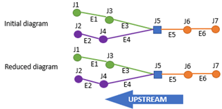 |
4. The schematic node reduction process can be set up according to the geometry of its incident links while the diagram junction reduction process cannot
The Route Node Reduction rule can be configured on schematic diagram templates to reduce schematic nodes with two connections when their adjacent links form a specific angle. This rule doesn’t apply to network diagram templates.
5. There is no way to iterate a sequence of Node Reduction rules when building a schematic diagram while it is possible on a sequence of Reduce Junction rules for a network diagram
| ArcGIS Desktop schematic diagrams | ArcGIS Pro network diagrams |
| Any node reduction rule runs individually as an iterative in-memory process, but there is no way to efficiently iterate on a node reduction rule sequence. You can repeat a rule sequence once or several times when configuring a diagram template, and this repetition can be sufficient to reduce all the nodes you expect in some diagrams. But there is no guarantee it will be enough for any generated diagrams. | Each Reduce Junction rule executes individually as an iterative in-memory process and the Start Iteration rule and Stop Iteration rule can be configured at the beginning and end of a Reduce Junction rule sequence to force the process to iterate on the rule sequence until there are junction candidates that can be reduced. |
Diagrams generated from trace results
Using trace results to build schematic diagrams
With ArcGIS Schematics, a schematic diagram can be generated from a tracing result returned as drawings in the geographic map. In this case, such a diagram keeps track of the starting point/barrier and trace parameter present in the map at its creation. Then, when updating the diagram, users can ask to re-run the trace in-memory and use this trace result as input for the update. This kind of update is specific to the diagram and decided at its creation.
Using trace results to build network diagrams
For network diagrams, you can configure traces to be run in-memory at diagram creation and update. This kind of configuration is set up on the diagram template using the Set Starting Point rule and Trace rule, and applies to any diagram related to this template.
ArcGIS Desktop schematic rules without corresponding ArcGIS Pro diagram rules or conversely
There are schematic rules without any corresponding ArcGIS Pro diagram rules or conversely. They are listed in the table below:
| ArcGIS Desktop schematic diagrams | ArcGIS Pro network diagrams |
| Expand Links rule | NA |
| NA | Reduce Edge rule |
| NA | Set Root Junction rule |
| NA | Add Diagram Feature Capability rule |
Create New Diagram Templates and Generate New Network Diagrams
In ArcGIS Pro, considering your newly migrated utility or trace network, it is time to create and configure the diagram templates you need to generate your new network diagrams.
You should work with the build and setting differences outlined above to determine whether these configurations are possible and how best to set up these new templates. The goal is to find the diagram rule sequence that will allow you to build network diagrams whose content will be as close as possible to those you generated with ArcGIS Schematics.
When these diagram templates are properly set up, you can generate the network diagrams you expect and store them with your trace or utility network dataset.
Port Schematic Diagram Layouts to New Network Diagrams
The last stage consists of porting the layout set up for some ArcGIS Desktop schematic diagrams to new ArcGIS Pro stored network diagrams. This should only concern a few schematic diagrams, specifically those that open with a nice layout that required meticulous manual editing.
To avoid repeating manual editing efforts on your new network diagrams, two standalone commands allow you to:
- Export your ArcGIS Desktop schematic diagrams layouts to JSON files,
- Import these JSON files to your new ArcGIS Pro network diagrams
During the export and import processes, the matching between each schematic feature in the ArcGIS Desktop schematic diagrams and the corresponding diagram feature in ArcGIS Pro network diagrams is done through Global IDs. These Global IDs are expected for each GIS feature in the ArcGIS Desktop dataset and must be preserved when importing these GIS features into the new ArcGIS Pro trace network or utility network feature classes.
These two standalone commands are provided as sample commands. They are downloadable with their source code and readme files from this location.
Conclusion
In the same way that there is no magic button to migrate your data to the utility network, there is also no way to automate the migration of your schematic diagrams to network diagrams. However, we hope this blog post will help you better understand the difference between schematic diagrams and network diagrams and give you enough guidance in porting ArcGIS Desktop schematic diagrams to ArcGIS Pro network diagrams.

Article Discussion: