ArcGIS Pro 2.3 has a lot of new functionality packed into it. After I finished dancing because spell check is now available for text elements on layouts, I also got really excited about enhancements made to north arrows.
Pro now supports magnetic north, and has some powerful new north arrow styles available.
These styles are SVG files, which use individual layers to make up a symbol. Each layer can be edited individually. So I can make the N on my north arrow red and all the other directions gray, without writing code or using another application.
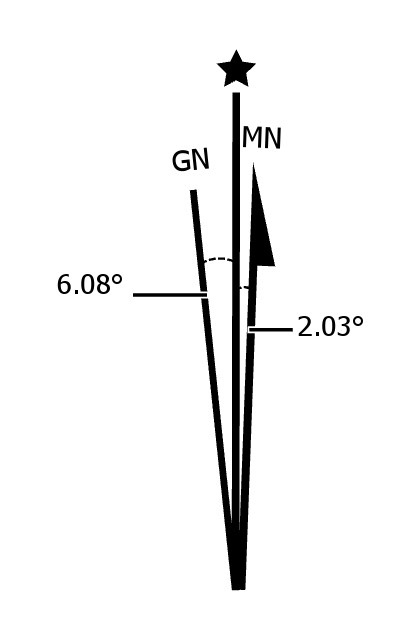
With the power of SVG and the new support for magnetic north, you can now build declination diagrams in Pro. These handy diagram show combinations of true north, magnetic north, and grid north; providing valuable information to map readers at a glance. They take a little time and effort to build, but are very doable. Here are the basic steps to create the diagram below, which you can follow and adapt to make your own unique and useful declination diagrams.

Step 1: Pick your layout
First pick a layout with a map frame. I’m using a map frame with a rotated map, to clearly see the difference between grid north and true north.
Step 2: Add north arrows
Next add the north arrows. I want my diagram to include true north, magnetic north, and grid north, so I need 3 north arrows (one for each type). I chose: True North 1, Magnetic North Right 1, and Grid North 1 from the north arrow gallery. Each of these styles is designed for declination diagrams, and points to the correct north type. IMPORTANT NOTE: If you use different north arrow styles, make sure the type is correctly set to true, magnetic, or grid north.
Step 3: Line ’em up
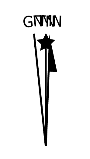
Move each north arrow so their endpoints line up on top of each other.

Now the declination diagram is starting to take shape, but the angles are hard to differentiate, the labels are on top of each other, and the lines are all the same size. It’s really not legible, and definitely not pretty. Here’s where those SVG styles become useful…
Step 4: Format
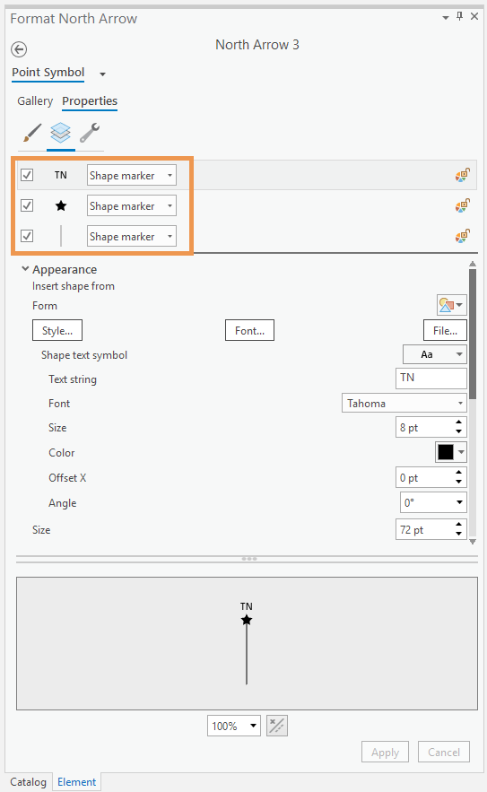
Select a north arrow and open its properties. Under the symbol properties and in the layers section there are different symbols like: text, star, and line. Each of these can be edited individually. Change the color or one, the text of another, turn pieces on and off, resize one symbol, offset another. The possibilities are endless!

Play with all the properties to get the look you want for your declination diagram. Here’s what I went with for mine (properties not listed were left as the symbol default):
True North
Text:
- Turned off
Star:
- Size: 62
- Offset Y: 25
Line:
- Size 148
Magnetic North
Text:
- Size: 74 (Size is located above Respect Frame)
- Y Anchor Point: -10%
Arrowhead:
- Size: 80
- Offset X: -1
- Offset Y: 6
Line:
- Size: 123
Grid North
Text
- Size: 74 (Size is located above Respect Frame)
- Y Anchor Point: -15%
Line:
- Size 105
Step 5: Angles
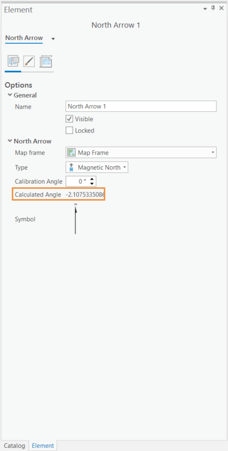
Add text to tell exactly how far magnetic and grid north are from true north. Thankfully, Pro calculates the angle for each north type so you don’t need to break out your protractor. Open the properties of any of the north arrows to see the calculated angle.

IMPORTANT NOTE: On a declination diagram the angle shown is the distance from true north to the magnetic or grid north. To get this you need to subtract the calculated magnetic or grid north angle from the true north angle.
I added curved lines to show the angles visually and drew my own leader lines to show which label belongs to which angle.
Step 6: Group it all together
Group your layers together. After all that work, the last thing you want is to try and move or resize your diagram, only to have lines go haywire and labels pointing to incorrect angles. To avoid this, select all the elements that make up the diagram in the Contents Pane, right-click and choose Group. Now when you move or resize the diagram it moves or resizes all the pieces correctly.
Step 7: Create styles to make this easier next time
Create new styles with all the formatting you just worked on. Then next time you make a declination diagram you can use these styles directly, skipping step 4. To save a style select each north arrow in the Contents pane, right click and choose Save to Style. Voilà, a brand-new style is available in the north arrow gallery! This north arrow style can now be added to any project.
Now you know the basics of making a declination diagram in Pro. Go on and have fun making your own!

Commenting is not enabled for this article.