With the release of ArcGIS Pro 2.6 and ArcGIS Enterprise 10.8.1 coming out later this month there are many updates and improvements to the utility network. The utility network has new capabilities that support nonspatial objects, changes to error management, the trace framework, and new options to improve subnetwork management.
Take note that a new version of the ArcGIS Utility Network is also available. Most of the changes described below are specific to version 4 utility networks that are created or upgraded using ArcGIS Pro 2.6.
Nonspatial support
Utility networks that you create or upgrade in ArcGIS Pro 2.6 now contain nonspatial junction and edge object tables.
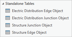
Junction and edge object tables are nonspatial network objects that are used to model and work with a large number of real-world features that share a common geographical space, for example, the strands inside a fiber cable or conductors in an underground duct.
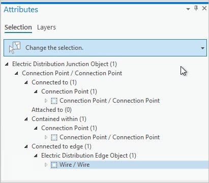
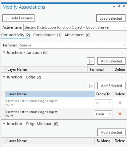
These nonspatial objects are related to other network features via associations and participate in the network for use with tracing and network diagrams. The revamped Modify Associations pane is used to establish associations as well as inspect any associations that may be in error.
Dirty area and error management changes
Previously, errors in the utility network were stored and visualized as individual features in sublayers of the utility network (point, line, and polygon errors). With Utility Network version 4, the dirty areas sublayer is now used to represent and manage errors generated by the system when a feature in the utility network is in violation of network rules and restrictions. This results in a change in how you work with errors using the dirty area sublayer.
The symbology of the dirty areas sublayer uses the status field to categorize the dirty area based on the type of operation that created it.
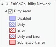
A Status Description field is displayed in the pop-up expression that provides information about the operation that created the dirty area. This is based on the Status field which uses bitwise encoding to represent the operation that created the dirty area.
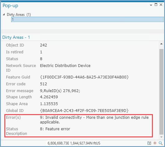
The Status Description and Error(s) fields contain additional information that indicates whether associated objects are in error. Associated features or objects in error are displayed with an orange indicator in the Modify Associations pane, along with a ToolTip containing additional information.
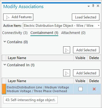
In ArcGIS Pro 2.6 and Utility Network version 4, dirty associations are denoted by a purple indicator in the Modify Associations pane. Dirty areas are no longer generated for the association as a linear dirty area between the features. Dirty areas are still created for individual junction features for connectivity and structural attachment associations in the map.
Trace framework updates
There have been many updates and improvements made to the trace framework with this release, from expanding support for nonspatial objects to the addition of new options and parameters to work with and control trace results.
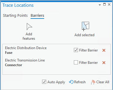
The trace framework has been updated to support nonspatial objects. In ArcGIS Pro 2.6 and Utility Network version 4, you can work with the Trace Locations pane to place starting points and barriers on nonspatial junction and edge objects and return these in the results of a trace.
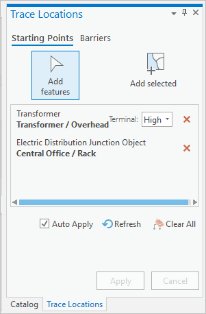
The trace tool has been updated with many new options and parameters that provide additional control over how features are traversed and output in the results of a trace.
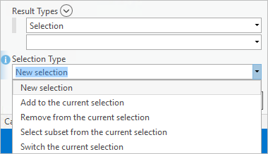
The new Result Types parameter provides support to output trace results into aggregated geometry feature classes. This capability also enables partial feature geometry to be returned in a trace. Aggregated geometry feature classes can be created to display the output of a trace in addition to, or instead of creating a selection set.
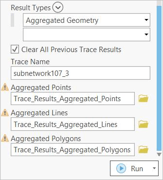
When working with selection sets, a new Selection Type parameter provides control over how a result is applied to the selection environment and defines the action to perform if a selection already exists.
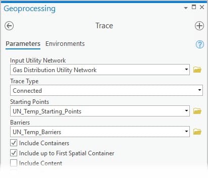
When used in conjunction with the Include Containers parameter, a new option, Include up to First Spatial Container, provides control over how results are returned in nested containment scenarios.
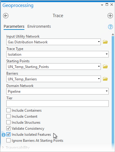
The Isolation trace has received many updates. Feature barriers can now be treated like filter barriers in subnetwork-based traces where they would otherwise restrict traversal from the trace starting points to the subnetwork controllers.
The Include Isolated Features parameter can be used to include the features that are traversable from the starting point(s) to the isolating features.
Subnetwork management updates
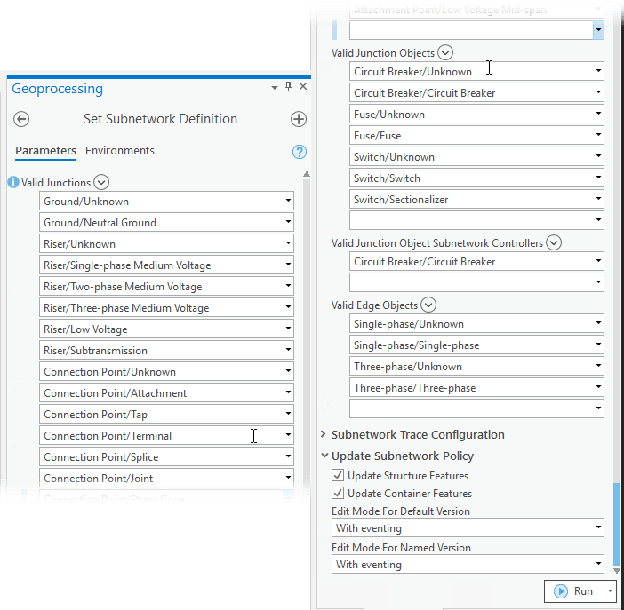
The subnetwork definition for a tier includes additional properties that aid in subnetwork management and control which features are valid to participate in the network. You can configure these options when you set or modify the subnetwork definition for a tier using the Set Subnetwork Definition geoprocessing tool. After configuration these options are used by the update subnetwork process:
Valid Features and Objects:
- Valid junctions are now configurable through the subnetwork definition, along with valid junction objects, valid edge objects, and valid junction object subnetwork controllers.
Update Subnetwork Policy:
- New options are available to define how the Update Subnetwork geoprocessing tool updates attributes in the default and named versions. These options control whether subnetwork attributes are updated with or without geodatabase events.
- New options control whether the supported subnetwork name attribute is updated for structure and container features during the update subnetwork process.
Subnetwork name attribute changes:
- The SUPPORTEDSUBNETWORKNAME field has been added to all domain network datasets (with the exception of the assembly feature class) to track the subnetwork name when features participate in, and support features that are in different subnetworks.
- The alias for the SUBNETWORKNAME field has been updated to Supported subnetwork name for all structure network datasets.
Export containment and attachment associations with a new Result Types option in the Export Subnetwork tool.
Additional changes worth checking out
- New connectivity association types
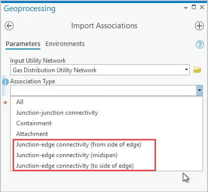
- Feature restrictions have been updated to support additional connectivity, containment, and structural attachment associations for the support of nonspatial objects and to provide additional flexibility modeling your data.
Visit the Utility Network community on GeoNet to continue the discussion and let us know which features you are most excited about with this release!







Commenting is not enabled for this article.